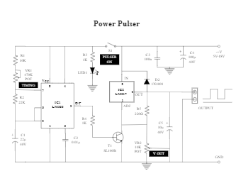
The idea of this multi-function power pulse generator is very simple.The circuit shown in Figure 1 USES a low-frequency oscillator to drive the voltage regulator.Timer chip LM555 (IC1) is connected to an unstable multivibrator.Components R1 and R2, VR1 and C1 generate free running frequencies.You can adjust it to some extent by changing the potentiometer VR1.The output of IC1 on pin 3 is controlled by the NPN transistor SL100B (T1) to adjust the on/off of the voltage stabilizer LM317T (IC2).


 Desktop