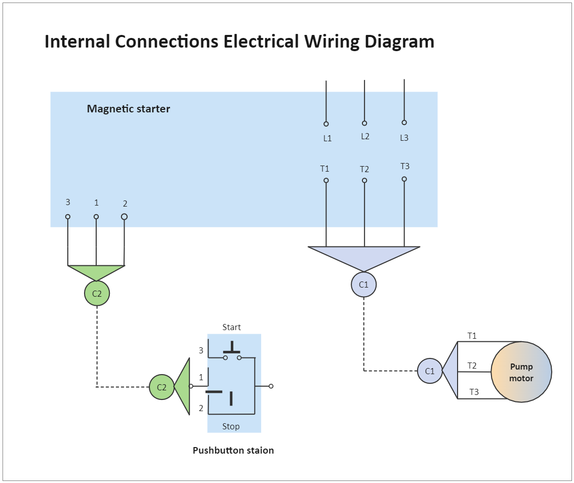
Internal Connections Electrical Wiring Diagram
2
0
0
publish time: 2021-01-06
This is an example of electrical wiring diagram for internal connections in power station. As the wire installed in the conduit C1, its size should be suitable for the current requirements of the motor. At the same time it is also part of the power circuit. The wire installed in the conduit C2 is a part of the low-voltage control circuit, and its size should meet the current requirements of the control transformer.
See More Related Templates

This is an example of electrical wiring diagram for a typical motor starter. From this diagram, it shows the internal details and connections of the right-hand device. The arrows and open terminals are the connections used by people.
4
0
0

This is an example of electrical wiring diagram about the control transformer ground system. The control transformer is properly grounded to the L2 side of the circuit. When the circuit works, the entire circuit on the left side of the coil M is an ungrounded circuit.
1
0
0

This is an example of electrical wiring diagram representing a mechanical function. The vertical dotted lines on the forward and backward buttons show that the normally closed contact and the normally open contact are connected. So, pressing the button will open one set of contacts and close another set.
3
0
0

This is an example of electrical wiring diagram for an alternative identification system. From this diagram, there is an alternative method to identify and arrange the wire numbers.
1
0
0

This is an example of electrical wiring diagram about a wiring numbering system. Some type of "wire identification" is required to correctly connect the control circuit conductors to their components in the circuit.
0
0
0

This is an example of electrical wiring diagram about the numerical system. The numbers in parentheses on the right side of the line graph show the line position and the type of contact controlled by the coil.
2
0
0

This is an example of electrical wiring diagram about rung number identification. From this diagram, there are 3 separate rungs, and the paths for these three rungs are totally different.
0
0
0

This parallel devices electrical diagram illustrates the control devices, from which it there contains push buttons, limit switches, switches, and pressure switches. The device usually starts with the parallel circuit.
3
0
0