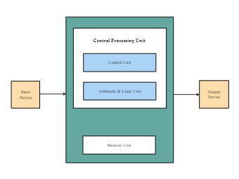
A block diagram is a diagram of a system where the principal parts or functions are represented by blocks connected by lines that shows the relationships of the blocks. The central processing block diagram shows the assembly of the input device, a central processing unit, and an output device. A Central Processing Unit has a memory unit, usually known as ROM or RAM; a control unit, and an arithmetic & logic unit that takes the data or information from the input device like keyboard or mouse. The central processing block diagram shows how the CPU performs the logic and prints the result on the output devices like an LCD screen or a printer. Instead of creating a central processing block diagram from scratch, use EdrawMax pre-defined templates as it provides the right facts and figures that ease the entire process.