We use a boost converter circuit when the i/p voltage is smaller than the required voltage so it will boost the voltage to the required input. So this project deals with a boost converter circuit that is based on two transistors.
What is a Voltage Booster Circuit?
Voltage Booster Circuit is such a circuit through which you can increase the DC voltage. Mainly this circuit works with an IC but we created it by just simply using Transistor.
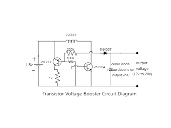
We are going to use two transistors, one is NPN i.e. 2N3904 and one is PNP i.e. 2N3906 for the switching purpose. The input voltage must be between 1.5V to 3.7V then you got the output voltage between 12V to 20V.
To get the fixed voltage at the output you can replace the value of the Zener Diode connect at the output of the circuit.
Components Required-
2n3904 Transistor
2n3906 Transistor
1k, 100k, 220k Resistance
1n4007 Diode
Zener Diode
220uH Inductor