Suppose you have a 12-volt battery and you want only 5 volts to test your circuit then what will you do? Surely you will use a 5-volt voltage regulator IC what wait! This can take a load up to of 1Amp.
Wait, a buck converter is a solution to your problem so you can easily Drop your input voltage without changing its efficiency.
Generally, we need a special IC to make a buck converter but here we use transistors to create the circuit.
What is a Buck Converter?
Buck converter is a circuit that drops the input voltage without changing the input voltage efficiency.
We can use buck converters in many projects such as the power bank, Variable power supplies, and many more.
Special IC is needed to make this circuit but there we create this circuit by using a set of transistors.
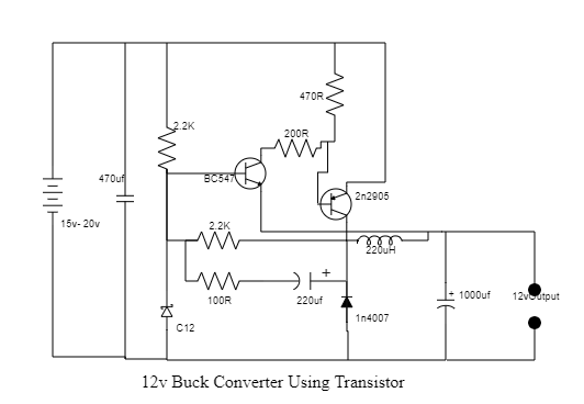
Components Needed:
1) BC547, 2n2905 Transistor
2) 470R, 200R, 100R, 2.2k Resistance
3) 470uf, 220uf, 1000uf Capacitor
4) C12 Shoot key Diode
5) 1n4007Diode
6) 220uH Inductor