Generally, in childhood, you saw a bigger radio set through with your grandfather listen to radio stations. Can we create such an FM radio receiver at home?
Yes, it is possible, with the help of fewer electronic components you can create such a circuit.
The sound quality of this circuit is very nice and the humming sound is cleared by filtering capacitors.
What is an FM Radio Receiver?
A radio or FM receiver is an electronic device that receives radio waves and converts the information carried by them to a usable form.
You can also increase its range by simply changing the size of the coil and the value of the variable capacitor.
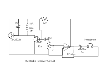
Here we use lm358 op-amp IC to increase the signal quality. You can use a dual op-amp for better results.
Components Needed;
1) LM358 op-amp
2) 2x 2n2222a Transistor
3) 22pf Variable Capacitor
4) 18AWG Copper Wire
5) 0.22pf, 0.1uf, Capacitor


 Desktop