If you see the price of a factory-made Power Bank module then it is very high as compared to a homemade one.
Yes, we can easily create a power Bank module circuit at home with some electronic components which you can find in the old scrap of the circuit board.
The output of this Power Bank module is approx. 2Amp which means you can easily charge the smartphone few hours.
What is a power bank module?
Power Bank modules are specially designed for the power banks to recharge our smartphone batteries fastly and safely.
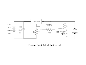
Power Bank module is a type of circuit that can give 5 volts at the output and the input must be between 5v to 9v.
With this power bank module, you have to connect around 6x 3.7-volt batteries in parallel to get the perfect current output.
Components Needed:
1) LM1086 IC
2) 120 Ohm, 1ohm, 1k Resistance
3) 5k potentiometer
4) 2x 100uf, 16v Capacitor
5) Led


 Desktop