An alternator is a maintenance-free yet the most important unit of the car's engine. It generates electricity, provides electrical supply to vehicles, and recharges the battery. The alternator works by converting mechanical energy into electrical energy from alternating current to the direct current.
The primary function is to work jointly with the battery to supply energy to the electrical components, i.e., lights, fan, windshield wipers, etc. It changes the alternating current into a direct current and regulates the voltage to meet the required minimum power for each unit.
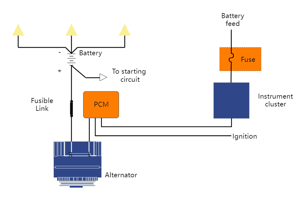
The powertrain control module voltage regulation circuits are an advanced type of alternator that uses internal modules to control the field circuit of an alternator. The PCM regulates the current flow by examining the data from the body control module (BCM) and understanding the charge needs of a system.
The PCR-controlled alternators are simple yet very efficient, generating the desired voltages. Whenever the voltage is below the desired value, the modules are triggered, and it changes the on-time of current flow through the coil. As a result, the system output is changed to adjust the system's needs.


 Desktop