
Templates Community /
Circuit Breaker Diagram
Circuit Breaker Diagram
Community Helper
Published on 2022-03-23

 Desktop

Introduction
A circuit breaker is a major device in the modern world. It can be operated manually and automatically and protect an electrical power system. As the modern power system deals with huge currents, special attention should be given to designing a circuit breaker to ensure it can safely interrupt the arc produced during the closing of a circuit breaker.
When the electrical wiring in a building has too much current flowing through it, this system cuts the power until somebody can fix the problem. Without circuit breakers, household electricity would be impractical because of the potential for fires and accidents resulting from simple wiring problems and equipment failures. The circuit breaker diagram will help us understand its functions in detail.
Keep reading to learn more about how EdrawMax Online helps create Circuit Breaker Diagram with free templates and design features.
1. Understanding Circuit Breaker Diagram
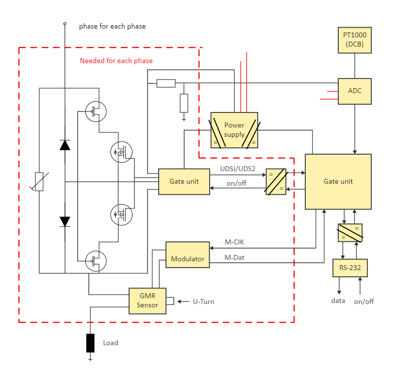
The circuit breaker diagram looks complex at first sight, but designing it becomes easier if we understand the function of each component in the circuit. The key components involve the gate unit, GMR sensor, modulator, power supply, control unit, PDC, and much more.
Gate Unit - Gate units are driver units used to manage Gate-turn-off. The control signal, transmitted via fiber optic, controls the output values from the gate unit. A remote indication signal can validate that the gate unit and GTO are functioning properly. This unit has been developed for traction systems and is currently being used successfully by numerous industries.
Modulator - Here, it superimposes a low-frequency signal onto a high-frequency signal. Higher frequency signals can be received using shorter aerials, which are more practical than longer ones. The information signal can be either analog or digital.
Control Unit - It receives input information to convert into control signals, which are then sent to the central processor.
2. How to Create a Circuit Breaker Diagram using EdrawMax Online?
Creating a Circuit Breaker Diagram in EdrawMax Online is pretty simple. The free Electrical Circuit maker has several features as you can instantly import the images or icons from your system, Google Drive, or DropBox. Your Electrical Circuit diagram will require additional media content, making it more creative.
Login EdrawMax Online Log in EdrawMax Online using your registered email address. If this is your first time accessing the tool, you can create your personalized account from your personal or professional email address.
Choose a template
EdrawMax Online comes with hundreds of free diagram templates. Select a pre-designed template by entering the Keyword in the "Search" section or exploring different diagram sets. In this case, you will find different types of Electrical Circuits diagrams under the "Electrical Engineering" section under the "Engineering" section. You will find different diagram sets, like Basic Electrical, Circuits and Logic, Industrial Control System, and Systems' Diagram. Alternatively, you can simply click on "+" in EdrawMax Online canvas to create a diagram of your preference.
Work on your research
As you can see from the Circuit Breaker Diagram below, the circuit Breaker consists of a fixed contact and sliding contact and moving contact. The moving contact moves into the sliding contact, shown in the figure.
Customize the diagram
Customize your Circuit Breaker Diagram by changing the color or adding more relevant data. You can also add or remove the Electrical Circuit symbols or content accordingly. Since it is about electrical engineering research, you can add more relevant data about different circuit diagrams.
Export & Share
Once your required circuit diagram is completed, you can share it amongst your colleagues or clients using the easy export and share option. You can further export the diagram in multiple formats, like Graphics, JPEG, PDF, or HTML. Also, you can share the designs on different social media platforms, like Facebook, Twitter, LinkedIn, or Line. In simple words, you can export your incredible Circuit Breaker Diagram to the files you want with just a few clicks.
3. Important Tips to Consider While Creating Circuit Breaker Diagram
Several tips need to be followed while designing or creating a circuit breaker diagram. Some of them are:
Show the positive and negative terminals of supply and their connections clearly in the circuit diagram.
Show through arrows the direction of the current flow.
Use dotted lines to show all device components in the circuit diagram.
The diagram must start from left and end towards the right, with input devices at the left side and output devices at the right end.
Make sure to connect the load to the GMR sensor in the circuit.
Mark the specifications of the components used in the circuit diagram.
Conclusion
The circuit breaker has to carry large-rated or fault power. Due to this large power, there is always dangerously high arcing between moving contacts and fixed contact during the operation of the circuit breaker. So, connect the components accurately in the system to avoid breakages. It is recommended to use EdrawMax Online to create Circuit Breaker Diagram for your projects. It should be noted here that since these circuit diagrams are the blueprints of the actual working models, ensure that you use the correct symbols provided by EdrawMax Online. Based on your research
Tag
circuit diagram
Circuit Diagram Collection
electrical plan
Share
Report
3
2.0k

Post
Recommended Templates
Loading
