
Templates Community /
PID Controller Basic
PID Controller Basic
Community Helper
Published on 2022-04-06

 Desktop

Introduction
PID controllers are devices used to regulate the temperature in a system. They are majorly used in industrial applications. Also, they have multiple uses in the chemical industry as they regulate pressure, speed, and other variables as well. The PID controller used a feedback mechanism to regulate the different variables in the system.
Let’s understand more about it through the PID controller basics circuit diagram and how EdrawMax Online aids in making some amazing PID Controller diagrams.
Understanding PID Controller Basics Circuit Diagram
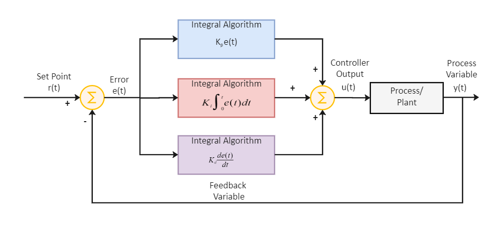
The PID Controller Basics circuit works based on proportional, integral, and derivative algorithms.
Proportional response - There is a preset value in the system and this component depends on the difference between the set value and the process variable. The difference generated is termed an error term in this system, and if we increase the proportional gain in this circuit, the control system’s speed will rise. But, if the proportional gain becomes too large, it starts oscillating.
Integral response - This performs the function of doubling the error term. The integral component will increase slowly even if a small error is generated. It keeps on increasing if the error term is not zero. So, the action plan here is to get the steady-state error zero.
Derivative Response - In case the process variable increases gradually, the output will increase. The control system will react more strongly to all changes in the error term. If the sensor feedback signal is noisy or if the control loop rate is too slow, the derivative response can make the control system unstable.
How to Create a PID Controller EdrawMax Online?
Creating a PID Controller Basics in EdrawMax Online is pretty simple. The free PID Controller maker has several features as you can instantly import the images or icons from your system or Google Drive, or DropBox. Your PID diagram will require additional media content, making it more creative.
Login EdrawMax Online
Log in EdrawMax Online using your registered email address. If this is your first time accessing the tool, you can create your personalized account from your personal or professional email address.
Choose a template
EdrawMax Online comes with hundreds of free diagram templates. Select a pre-designed template by entering the Keyword in the "Search" section or exploring different diagram sets. In this case, you will find different types of PID controllers under the "Industrial Process" section under the "Engineering" section. Alternatively, you can simply click on "+" in EdrawMax Online canvas to create a diagram of your preference.
Work on your research
Based on your research, you will learn that the PID Controller Basics is an instrument used in industrial control applications to regulate temperature, flow, pressure, speed and other process variables.
Customize the diagram
Customize your PID diagram by changing the color or adding more relevant data. You can also add or remove the PID Controlling symbols or content accordingly based on your research. Since it is about scientific research, you can add more relevant data about different PID diagrams.
Export & Share
Once your required PID diagram is completed, you can share it amongst your colleagues or clients using the easy export and share option. You can further export the diagram in multiple formats, like Graphics, JPEG, PDF, or HTML. Also, you can share the designs on different social media platforms, like Facebook, Twitter, LinkedIn, or Line. In simple words, you can export your incredible PID Controlling diagrams to the files you want with just a few clicks.
Important Tips to Consider While Creating PID Controller Basics Circuit Diagram
The steps are simple in the creation of the PID controller, especially the PID controller basics circuit. It will become much easier if you follow some other tips. Let’s look into those tips in detail below.
Proportional, integral, and derivative algorithms must be connected in parallel to each other.
The error signal generated must be fed as the input to the different responses.
Mark the algorithm of each response system in the box itself.
Mark the flow of current and supply throughout the system.
The feedback variable, if any, must be clearly indicated in the circuit diagram.
Conclusion
By combining the three response systems of PID, we can regulate the temperature, speed, and other variables. It works on the feedback mechanism and has wide applications in various segments worldwide. Use EdrawMax Online to create a better-looking PID Controller diagram for your company’s usage.
Tag
Utility-Generation P&ID
Share
Report
4
517

Post
Recommended Templates
Loading
