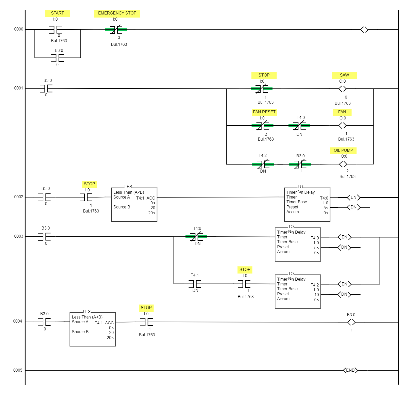
A ladder logic diagram is a symbolic representation of the control logic used in PLC programming. Ladder diagrams comprise the horizontal lines of control logic called rungs, and vertical lines at the beginning and end of each rung are called rails. It resembles a ladder, hence the name "ladder diagram." The M1 START pushbutton input is used in the Ladder Logic Diagram example to activate the M1 RUN output. A second time, the M1 RUN output is used to latch the M1 RUN output. Because M1 STOP and M1 TOL are wired normally closed (NC) to the PLC inputs, they must be configured in the logic as normally open (NO) symbols.


 Desktop