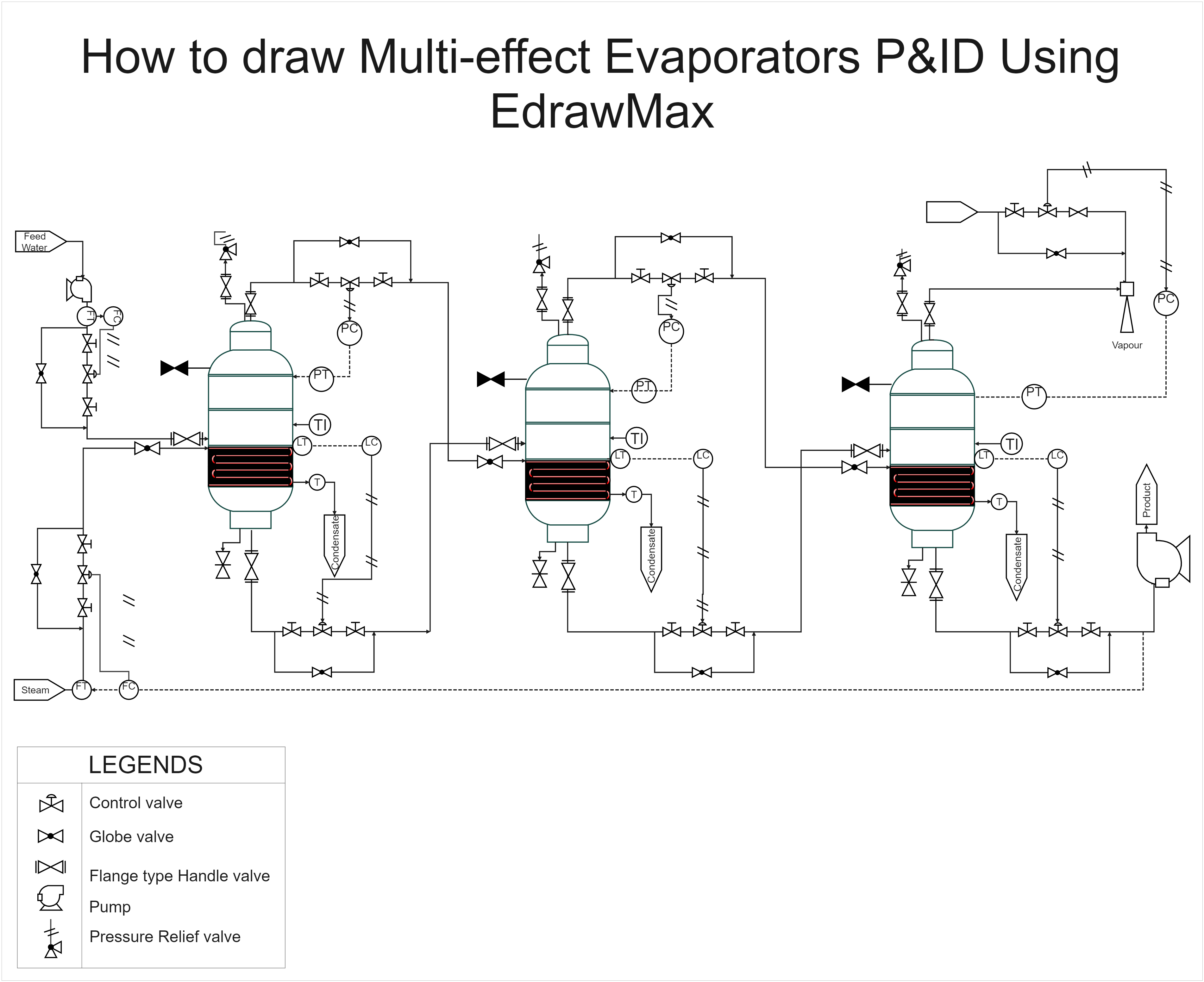
This is a P&ID diagram for a Multi-effect Evaporator. Evaporators are divided into two sections: the heating portion (also known as the steam chest) and the vapor/liquid separation section. These components can be housed in a single vessel (body), or the heating section can be housed outside of the vessel that contains the vapor/liquid separation section. P&ID is an excellent design for demonstrating how a multi-effect evaporator works. The acronym P&ID stands for 'Piping and Instrumentation Diagram.' P&IDs use industry-standard engineering notation to highlight the necessary instruments, equipment, pipe, and interconnecting lines. Diagrams depict particular processes inside a plant or industrial facility, containing symbols for actuators, equipment, flow elements, sensors, pipe fittings, valves, and other components.
EdrawMax is the P&ID Diagram software available because it offers extensive features and shapes relevant to any need.


 Desktop