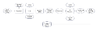
This Water Treatment Process Flow Diagram, created with EdrawMax, illustrates the complete system flow from inlet to outlet sampling. It includes key components such as separator, filter, backflush pump, UV reactor, flow control valve, and monitoring devices like pressure transmitters and flowmeters. The system is centrally managed by a control cabinet and supported by electrical units for real-time performance control. This diagram is ideal for engineers, system designers, and operators in the environmental or industrial water treatment sector, offering a clear overview of each stage in the fluid purification process.