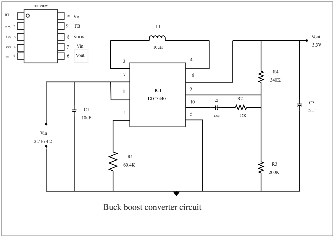
Buck-boost converter circuits are powerful and versatile systems that provide flexibility to various electrical applications. These types of converters convert an input voltage to either a higher or lower level depending on their design. Buck-boost converters are indispensable in all kinds of power supplies, providing a reliable means of boosting or dropping the input voltage to suit the electrical requirements of the device in use. A Buck-Boost Converter Circuit is a type of DC-to-DC converter that can take an input voltage and either increase or decrease its magnitude without changing its polarity. This is accomplished by using a switching circuit along with an inductor, diode, and capacitor to control the output voltage. This type of circuit is useful for applications that require varying output voltages from a fixed input voltage source. Easily recreate similar elaborated diagrams using the free template and systems provided by EdrawMax.


 Desktop