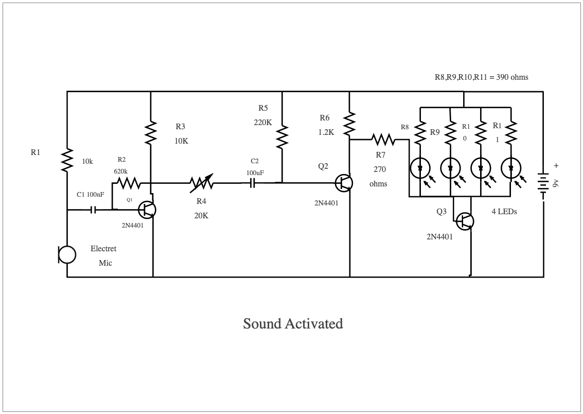
A sound-activated switch circuit diagram is a schematic illustration of the wiring and components needed to construct a sound-activated switch. This type of switch senses sound in the environment and activates or deactivates in response. The circuit diagram will typically include diagrams for the power supply, audio amplifier, microphone, and other relevant components. Additionally, it will also illustrate how to make all the necessary connections between them to create a functioning sound-activated switch circuit. A sound-activated switch is a circuit that can be used to turn on or off an electrical device when it detects sound. It works by sensing the loudness of an audio signal, such as a clap or a whistle, and using that information to activate a relay. This type of switch can be used in applications such as child access toys, musical instruments, and home automation systems. The circuit diagram for this switch typically involves using the Output pin of microphone amplifiers connected to a transistor. Easily recreate similar elaborated diagrams using the free template and systems provided by EdrawMax.


 Desktop