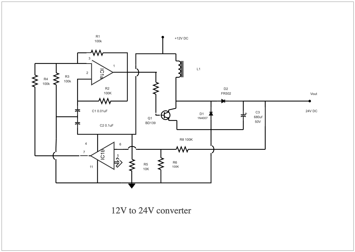
A 12V to 24V converter circuit diagram can be used as a guide for creating a converter circuit that converts 12 volts of direct current (DC) electricity into 24 volts of DC electricity. This type of circuit is often found in electronic systems, such as power supplies and other power-related applications. The circuit typically consists of two resistors, two diodes, and one transistor, all arranged in specific configurations to create the necessary output voltage. A 12-volt to 24-volt converter circuit diagram is a schematic representation of how a 12-volt source can be transformed and converted into a 24-volt output. This process involves the use of various electrical components such as resistors, capacitors, transistors, and other necessary elements. When correctly connected, it will provide consistent 24 voltage for control panels. Easily recreate similar elaborated diagrams using the free template and systems provided by EdrawMax.


 Desktop