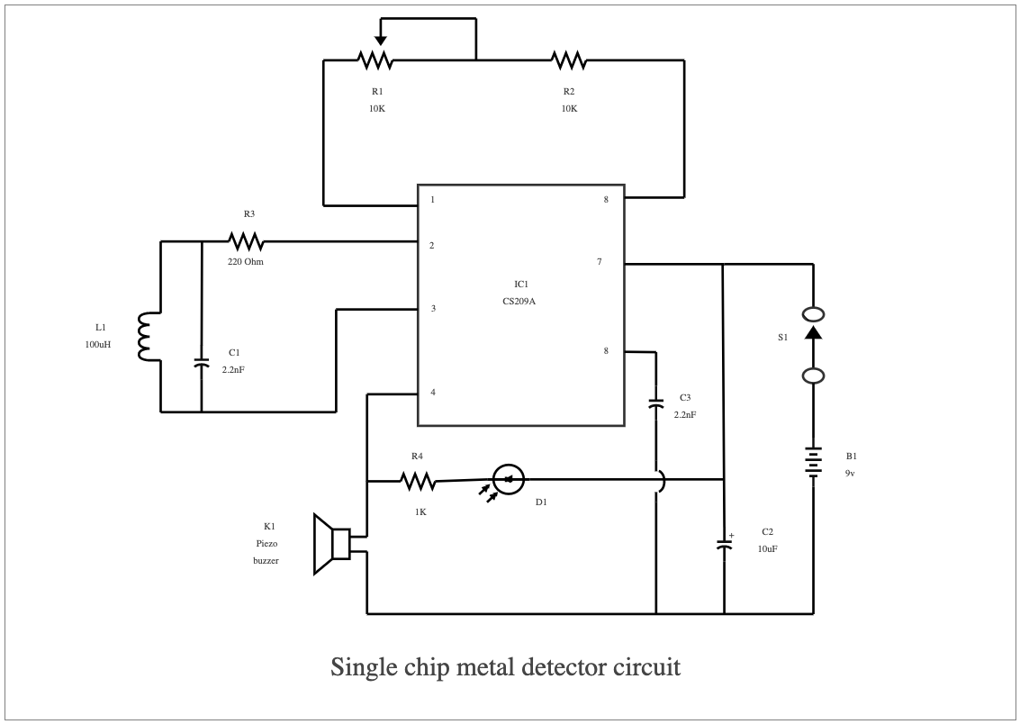
A single-chip metal detector circuit diagram provides a visual representation of the components and connections used to create a detector that detects metals. This diagram typically includes symbols for all the components – such as transistors, resistors, capacitors, and inductors – as well as the connections between them, allowing users to create their own version of the device easily. Additionally, an electronic schematic may include details about operation and performance specifications for each component or link in the circuit. Single-chip metal detectors are powerful, cost-effective sensors that can detect the presence of a metallic object. They are sometimes used on production conveyors to help detect potentially hazardous items or unwanted metals that could pose a threat to the safety of workers. These single-chip circuits contain an inductor coil connected to a circuit board, with pins and tracer wires positioned along the board layout, allowing the detector to measure changes in electric fields that indicate the presence of metal. Easily recreate similar elaborated diagrams using the free template and systems provided by EdrawMax.


 Desktop