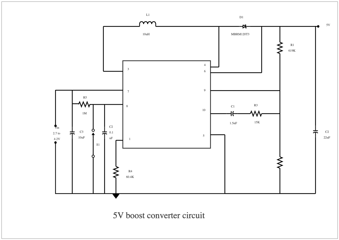
A 5-volt boost converter circuit is a useful tool for converting low-voltage signals into higher-voltage signals. The basic design components of the circuit include an input switch, an inductor, a diode, a capacitor, and an output transistor. All of these components interact within the circuit to create a voltage boost from the initial input signal to a higher output signal. The connection of these components must be done in such a way as to ensure the proper functionality of the final circuit. A 5-volt boost converter circuit is a DC-to-DC converter that increases the output voltage above the source voltage. This type of circuit is particularly useful in situations where the source voltage may be too low when starting up, allowing the user to reduce the number of cells and increase the output voltage. A diagram of this circuit is available online and shows how it works to convert an input signal into a higher output signal. Easily recreate similar elaborated diagrams using the free template and systems provided by EdrawMax.


 Desktop