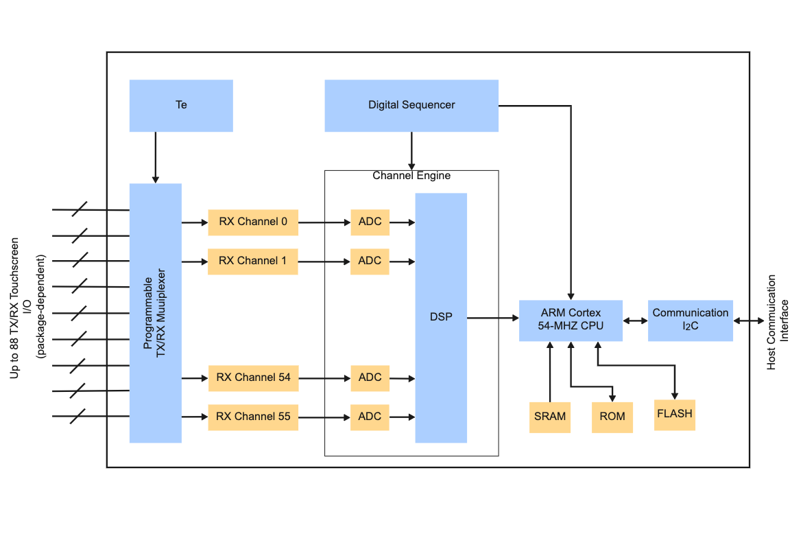
A block diagram for a communication system is a graphical representation of the various components that make up the whole system. It is an important tool used by testers to visualize and evaluate the design of a particular architecture, as well as identify potential issues that may arise. Through this diagram, testers can gain insights into the complex network of interactions between the different components in a given system, helping them determine its overall effectiveness. As you can see, a communication system block diagram is a schematic representation of the various components and connections involved in a communications system. It is used to illustrate how the components interact, allowing engineers and other users to understand how the system works and what it needs to operate successfully. A typical block diagram will include inputs, outputs, encoders, decoders, modulators, multiplexers, transceivers or transponders, antennas, and receivers. These components can be represented in various ways depending on their functions and connections within the communication system. Use EdrawMax to create and download this template for your work.


 Desktop