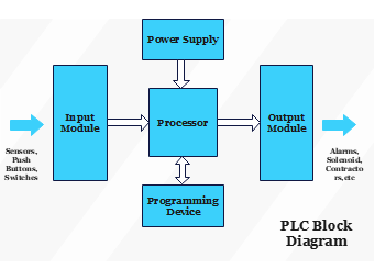
This EdrawMax template illustrates a basic PLC Block Diagram, essential for understanding the core components and flow of a Programmable Logic Controller system. It features a 'Power Supply' that energizes the entire system, an 'Input Module' for collecting signals from sensors, pushbuttons, and switches, and an 'Output Module' which triggers actuators like alarms and solenoids. At the heart of the system lies the 'Processor', which interprets input signals and executes logic, and a 'Programming Device' used for setting up and altering the PLC's program. This diagram is a fundamental tool for electrical engineers, automation professionals, and students learning about automated control systems, offering a clear depiction of how PLCs operate within industrial settings.


 Desktop