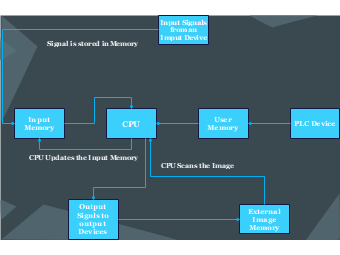
This EdrawMax template showcases a detailed workflow of a Programmable Logic Controller (PLC), highlighting the interaction between its core components for efficient automation control. The process begins with 'Input Signals' from an input device stored in 'Input Memory'. The 'CPU' plays a central role, updating the 'Input Memory' and scanning the system's current state or 'Image'. 'User Memory' and 'External Image Memory' are essential for storing user-defined programs and external data, respectively. The 'Output Signals' are then sent to output devices, finalizing the control sequence. This detailed diagram is indispensable for understanding the PLC's internal processes, making it a crucial resource for automation engineers, system designers, and educational purposes in automation technology.


 Desktop