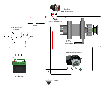
This circuit illustrates the wiring configuration for a 3-way alternator with a voltage regulator and an ignition switch. The alternator plays a crucial role in a vehicle's charging system, converting mechanical energy into electrical energy. In this setup, the alternator is connected to the battery and the vehicle's electrical system using three wires: the main power wire, the sensing wire, and the field wire. The main power wire charges the battery and powers the vehicle's electrical components. The sensing wire monitors the battery voltage and regulates the alternator's output. The field wire controls the alternator's output voltage and is regulated by the voltage regulator. The ignition switch is connected to the alternator, allowing the alternator to be activated when the switch is turned on. This wiring arrangement ensures efficient charging of the battery and proper operation of the vehicle's electrical system.