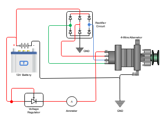
This circuit demonstrates the wiring setup for a 4-way alternator with a rectifier circuit and a voltage regulator. The alternator is a crucial component in a vehicle's charging system, converting mechanical energy into electrical energy. In this setup, the alternator is connected to the battery and the vehicle's electrical system using four wires: the main power wire, the sensing wire, the field wire, and the rectifier output wire. The main power wire charges the battery and powers the vehicle's electrical components. The sensing wire monitors the battery voltage and regulates the alternator's output. The field wire controls the alternator's output voltage. The rectifier circuit converts the alternator's AC output into DC, which is required for charging the battery. The voltage regulator ensures that the alternator's output voltage is within the acceptable range.


 Desktop