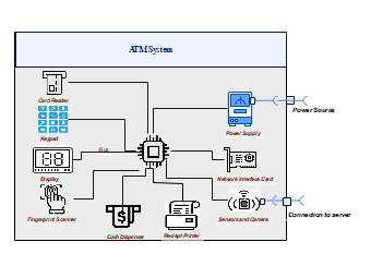
In the following block diagram of an ATM Withdrawal system, there is a big square box representing the system that houses the CPU. The CPU is the control unit and is responsible for coordinating all system functions and interactions. Important components connected to the CPU include: card reader, keypad, display, fingerprint scanner, cash dispenser, receipt printer, sensor and camera, network interface card and power supply. Each component plays a critical role in the operation of an ATM machine, facilitating tasks such as user authentication, and transaction processing. This diagram provides a visual representation of the relationship between these components, showing the functionality and capabilities of ATM.