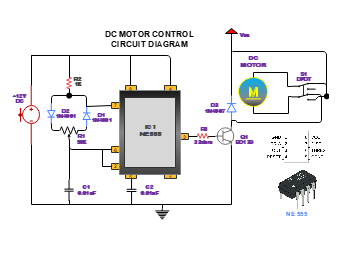
This DC motor circuit is used to control the speed. It consists of various electrical components such as Resistors, Capacitors, Diodes, Potentiometer, IC1NE555, AC source, and Switches. Our circuit is molded around the IC1NE555 and PWM is used to change the velocity of motors. Transistors are used to amplify the current flow whereas diodes help with the unidirectional path of the motor. This DC motor circuit diagram shows the users how a controlling circuit for a DC motor can be designed and enables the users to gain an understanding of its functionality.


 Desktop