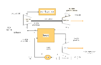
This is a Combined Cycle Power Plant Process Flow Diagram Template. It illustrates the structure of a combined cycle power plant, featuring components like a compressor, combustor, gas turbine, heat exchanger, vapor turbine, pump, and condenser, with parameters such as efficiencies (eta_c=.84, eta=.88) and pressures/temperatures (p3=p2=1200kpa, t=1400k). Ideal for power engineers, energy analysts, or plant designers, this template visualizes the process flow of gas and vapor cycles to aid in power plant design, efficiency analysis, and operational planning.


 Desktop