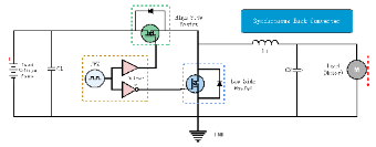
This is a Synchronous Buck Converter Circuit Diagram Template. It details the circuit structure for voltage conversion, featuring high-side and low-side MOSFETs, PWM drivers, inductor, capacitors, and a motor load, with synchronous switching enabling efficient step-down voltage regulation. Ideal for power electronics engineers, motor control designers, or embedded system developers, this template helps visualize and understand the circuit design for synchronous buck conversion in motor and power supply applications.


 Desktop