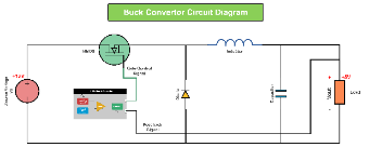
This is a Buck Convertor Circuit Diagram Template. It details the circuit structure for converting 12V input to 5V output, featuring components like an NMOS, PWM signal generator, inductor, diode, capacitor, and load, with the PWM signal controlling the NMOS to regulate voltage through energy storage and release in the inductor. Ideal for power electronics engineers, embedded system developers, or power supply designers, this template helps visualize and understand the circuit design for step - down voltage conversion.


 Desktop