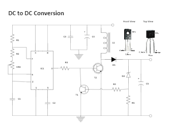
The DC-to-DC conversion circuit is constructed with the very popular IC LM555 to generate the required frequency range of 2 to 10 kHz to drive the power transistor T2. The potentiometer VR1 is used to adjust the given output frequency, the transistor T2 passes through the resistor R3, and the Zener diode in the circuit is used as a voltage regulator.


 Desktop