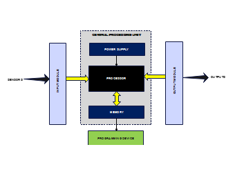
A Programmable Logic Controller or PLC block diagram has sections for inputs for signal acquisition, communication or storage unit, devise for control program execution, and sections for output for command implementation. The board also has provisions for the power supply and communication interfaces that interface the system. It is the control model of the PLC since it interprets the inputs before controlling the outputs.


 Desktop