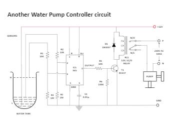
The water pump controller senses the water level in the water tank and drives the water pump. The circuit described here is built around timer IC1 (555). When the water tank level is lower than the low level marked "L", the voltage of IC1 pin 2 becomes low. The internal SR flip-flop of IC1 is reset and its output becomes high. This high output pin 3 of IC1 drives the relay driver transistor T1 (BC547) and powers the relay RL1. The water pump gets power through the n/o contact of the relay and turns on the power to start filling the water tank.