shadow
Template Community / Circuit Diagram of Infrared Remote Control

Circuit Diagram of Infrared Remote Control

EdrawMax user profile image
Circuit Everyday
Published on 2020-09-25
Download
Download
Download EdrawMax
Edit Online
logoanimation
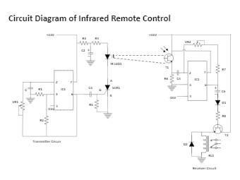
The phototransistor receives the transmitted signal and provides it to pin 2 of IC2 for amplification. The amplified output from IC2 pin 6 is provided to the base of the relay driver transistor (T2) through the non-polarized capacitor C5, diode D1 and resistor R8. The variable resistor VR1 is used to match the transmitted and received signals.
Tag
circuit diagram
circuit
infrared remote cont
Report
1
90
EdrawMax user profile image
Post
Recommended Templates