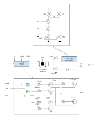
In a buffer system, time to live (TTL) refers to the amount of time or ‘hops’ that a packet is set to exist inside a network before being discarded by a router. Trace Route works by setting the TTL for a packet to 1, sending it towards the requested destination host, and listening for the reply. A block diagram can be used simply to represent the composition and interconnection of a system. As per the TTL Input and output buffer block diagram, it can also be used together with transfer functions to represent the cause-and-effect relationships throughout the system. The transfer function is defined as the relationship between an input signal and an output signal to a buffer system. Create TTL input and output buffer block diagrams by using in-built tools from EdrawMax or EdrawMax Online.