Wireless Tester Circuit
Generally, we use a multimeter to check weather the circuit is working or not and where the connections are broken or not. But here in this article we are going to learn about such a circuit through which you can test the various connections without making contact with it.
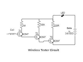
All the details linked to this circuit is given in the article, Such as Schematic diagram, components list.
What is a Wireless Tester Circuit?
This circuit can be used to test whether mains voltage is present or not without having electric contact with mains line.
Only using 3 transistors you can create this circuit. Here am using a NPN Bipolar Transistor i.e. BC547.
What Material Required to make this project?
• Any 3x NPN Transistor i.e. BC547
• 220 ohms, 100k ohms, 1M ohms Resistance
• Any color LED
• Coil
• 9VDC power source


 Desktop