If you want to buy a factory-made buck converter then you have to pay a lot for that. But there is a solution for that; you can also make your own homemade converter by just using a 555 timer IC.
Simply with the help of some other components, you can create an effective buck converter that would work the same as a factory-made.
What is a buck Converter?
Generally, the buck converter is a device that can reduce the output current as compared to the input current but the efficiency of current remains the same.
OR
Buck converter is a device through which we can regulate the voltage but the efficiency of voltage does not drop.
Generally, we use a specialized IC for the buck converter circuit but here in the circuit be used only a 555 timer IC and some other components to create this circuit.
The efficiency of this circuit is about 90%. If you are using a load greater than 1 Ampere at output then use a suitable heat sink with the MOSFET.
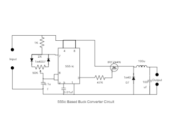
Components Needed:
1) 555ic
2) 3x 1n4007diode
3) 1k, 47ohm Resistance
4) 50k Potentiometer
5) 0.1uf, 0.01uf, 100uf Capacitor
6) Irfz44n Mosfet
7) 100uH Inductor