Creating a metal detector circuit having great fun because through it you can easily detect metal. Here in the circuit, we use a transistor to make it easier to make.
If we increase the diameter of the copper coil then its power of detecting metal will increase.
This circuit is a simple prototype circuit to test the waveform when metal is that near to the copper coil.
When we connect an oscilloscope to this circuit and get a metal nearer to the circuit then the oscilloscope shows the bigger waveform.
What is a metal detector Circuit?
Metal detector circuit which contains copper coil and when a metal is kept near to this copper coil, the oscilloscope shows the change in the waveform.
A simple circuit which is made up of transistor and few More components which are easily found in old scrap circuit.
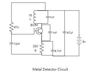
Components Needed;
1) BC 547 Transistor
2) 220R, 47k Resistance
3) 2x 1nf, 10nf, 4.7nf, 47uf Capacitor
4) Buzzer


 Desktop