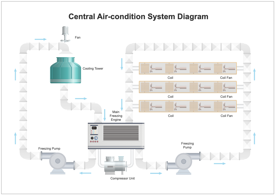
The Central Air-Condition System Diagram is a visual representation of the components and flow of a central air conditioning system. The diagram includes important components such as the compressor, freezing pump, and cooling tower. The compressor is responsible for compressing refrigerant and circulating it throughout the system, while the freezing pump removes heat from the refrigerant, causing it to become cold. The refrigerant then moves to the cooling tower, where it is cooled by circulating water. This cool refrigerant is then sent to the evaporator coils to cool the air that is distributed throughout the building. The purpose of the Central Air-Condition System Diagram is to provide a clear understanding of the components and flow of a central air conditioning system, making it easier to troubleshoot and maintain the system. This diagram is a useful tool for HVAC professionals, building engineers, and maintenance personnel who are responsible for ensuring the proper operation of air conditioning systems in commercial and industrial buildings. EdrawMax is the best diagramming tool to create similar diagrams. Download EdrawMax today and start customizing similar templates.


 Desktop