
Templates Community /
Circuit Setter Piping Diagram
Circuit Setter Piping Diagram
Community Helper
Published on 2022-03-23

 Desktop

Introduction
The piping diagram is commonly used in the engineering field, and it shows the piping and related components of a physical process flow. Piping diagrams are foundational to the maintenance and modification of the process that it graphically represents. The diagram also provides the basis for developing system control schemes at the design stage. They are typically created by engineers designing a manufacturing process for a physical plant. They are used by field techs, engineers, and operators to understand better the process and how the instrumentation is interconnected. They can also be useful in training workers and contractors. Let's try to understand more about the Circuit Setter Piping Diagram here.
Keep reading to learn more about how EdrawMax Online helps create Circuit Setter Piping Diagrams with free templates and design features.
1. Understanding Circuit Setter Piping Diagram
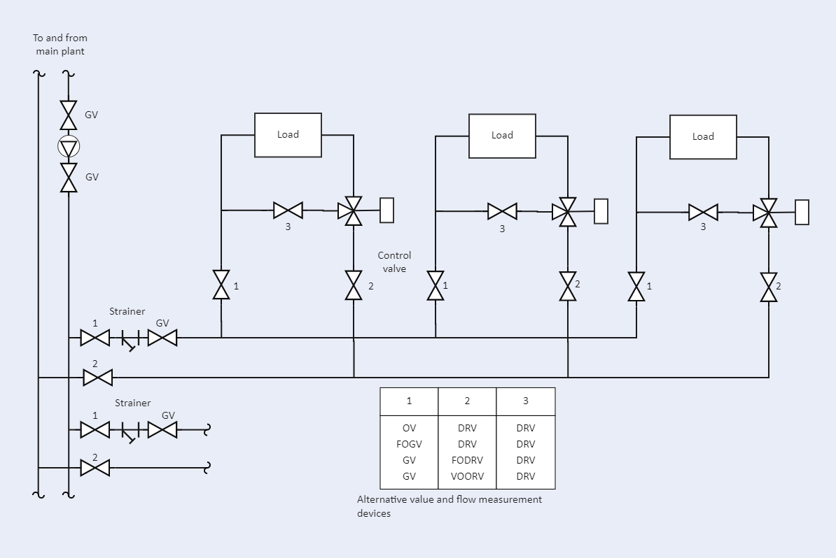
The Circuit Setter Piping Diagram comprises a filter, load, and control valve.
Equipment – tanks, vessels, heat exchangers, pumps, compressors, columns, etc., are indicated with type, reference tag numbers, basic design data, spares, and more.
Lines – reference tag numbers, piping material class, line size, fluid service, insulation type, and thickness, etc., are also represented on the circuit diagram.
Some other piping requirements such as slope, special insulation such as heat tracing are also shown on the circuit.
Drains and Vents are usually indicated using typical symbols and their size and type.
Automated valves – Shutdown valves (SDV), control valves, blowdown valves (BDV) are indicated with size if it is known.
Safety Valves – Pressure relief valve (PRV) or Temperature relief valve (TRV) are indicated with their instrument tag numbers, setpoints, types are indicated by different symbols.
2. How to Create a Circuit Setter Piping Diagram using EdrawMax Online?
Creating a Circuit Setter Piping Diagram in EdrawMax Online is pretty simple. The free Electrical Circuit maker has several features as you can instantly import the images or icons from your system, Google Drive, or DropBox. Your Electrical Circuit diagram will require additional media content, making it more creative.
Login EdrawMax Online
Log in EdrawMax Online using your registered email address. If this is your first time accessing the tool, you can create your personalized account from your personal or professional email address.
Choose a template
EdrawMax Online comes with hundreds of free diagram templates. Select a pre-designed template by entering the Keyword in the "Search" section or exploring different diagram sets. In this case, you will find different types of Electrical Circuits diagrams under the "Electrical Engineering" section under the "Engineering" section. You will find different diagram sets, like Basic Electrical, Circuits and Logic, Industrial Control System, and Systems' Diagram. Alternatively, you can click on "+" in EdrawMax Online canvas to create a diagram of your preference.
Work on your research
As you will see from the Circuit Setter Piping Diagram below, a circuit setter valve is used to optimize the pressure between hot and cold water within the potable water system when it comes to plumbing. The earlier trends were to use a check valve and a ball valve.
Customize the diagram
Customize your Circuit Setter Piping diagrams by changing the color or adding more relevant data. You can also add or remove the Electrical Circuit symbols or content accordingly based on your research. Since it is about electrical engineering research, you can add more relevant data about different circuit diagrams.
Export & Share
Once your required circuit diagram is completed, you can share it amongst your colleagues or clients using the easy export and share option. You can further export the diagram in multiple formats, like Graphics, JPEG, PDF, or HTML. Also, you can share the designs on different social media platforms, like Facebook, Twitter, LinkedIn, or Line. In simple words, you can export your incredible Circuit Setter Piping diagrams to the files you want with just a few clicks.
3. Important Tips to Consider While Creating Circuit Setter Piping Diagram
Some tips will help you in the creation of the circuit diagram. Well, more than tips, they are points to be noted while designing the circuit or the diagram. They will help users in clearly understanding the connection and their use cases.
Make a clear connection and mark the name of each component in the circuit diagram.
Make sure to connect the load across all diodes.
Connect the circuit to the ground to avoid any breakages
Conclusion
Circuit Setter Piping Diagram is a schematic illustration of the functional relationship of piping, instrumentation, and system equipment components used in the field of instrumentation. They are used by field techs, engineers, and operators to understand better the process and how the instrumentation is interconnected. It is recommended to use EdrawMax Online to create Circuit Setter Piping diagrams for your projects. It should be noted here that since these circuit diagrams are the blueprints of the actual working models, ensure that you use the correct symbols provided by EdrawMax Online.
Tag
logic diagram
Share
Report
5
1.6k

Post
Recommended Templates
Loading
