
Template Community /
Full Adder Circuit Diagram
Full Adder Circuit Diagram
Community Helper
Published on 2022-03-23

Introduction
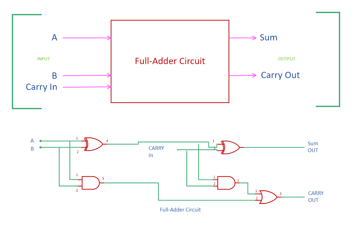
As the name says, a full adder is an adder that takes three inputs to produce two outputs, that is, sum and carry out. The inputs A and B are added along with carrying IN to generate the output in this adder. It differs from half adder as they have two inputs and two outputs. In electronic devices, an adder is used to perform addition. Different gates are used to create this circuit diagram. Let's look into its functioning in detail through the full adder circuit diagram.
Keep reading to learn more about how EdrawMax Online helps create Full Adder Circuit Diagrams with free templates and design features.
1. Understanding Full Adder Circuit Diagram
From the truth table of the full adder circuit,
When the three input bits applied are zero, the outputs, both sum and carry-out, are zero.
The sum output is 1 when only one of the input bits applied is 1 or when all the bits applied are 1.
The carry-out can be 1 if two or three inputs applied are 1.
Full adders are constructed using the basic logic gates. Even the combination of half adders can also lead to the formation of this adder. The equation for the output terminal of the sum is the exclusive operation performed on all the three inputs A, B, and Carry-in. Once the equations are obtained, the logic diagram for the adder circuit is designed.
The two gates of XOR and AND followed by one OR gate can be utilized to construct the full adder circuit diagram. The circuits comprise two half-adder circuits. The purpose of the initial half adder is to generate the sum and carry, but the carry-in is added at the next half adder circuit such that the final output is generated. The carry generated after the process in the half adder circuit is the OR function that obtains the final output for carrying. The implementation of this circuit becomes complex compared to the half-adder circuit as well as it increases the time required for the propagation of bits through the gates.
2. How to Create a Full Adder Circuit Diagram using EdrawMax Online?
Creating a Full Adder Circuit Diagram in EdrawMax Online is pretty simple. The free Electrical Circuit maker has several features as you can instantly import the images or icons from your system, Google Drive, or DropBox. Your Electrical Circuit diagram will require additional media content, making it more creative.
Login EdrawMax Online
Log in EdrawMax Online using your registered email address. If this is your first time accessing the tool, you can create your personalized account from your personal or professional email address.
Choose a template
EdrawMax Online comes with hundreds of free diagram templates. Select a pre-designed template by entering the Keyword in the "Search" section or exploring different diagram sets. In this case, you will find different types of Electrical Circuits diagrams under the "Electrical Engineering" section under the "Engineering" section. You will find different diagram sets, like Basic Electrical, Circuits and Logic, Industrial Control System, and Systems' Diagram. Alternatively, you can simply click on "+" in EdrawMax Online canvas to create a diagram of your preference.
Work on your research
As per the Full Adder Circuit Diagram, a full adder is a digital circuit that performs addition. Full adders are implemented with logic gates in hardware. A full adder adds three one-bit binary numbers, two operands, and a carry bit.
Customize the diagram
Customize your Full Adder Circuit diagrams by changing the color or adding more relevant data. Based on your research, you can also add or remove the Electrical Circuit symbols or content accordingly based on your research. Since it is about electrical engineering research, you can add more relevant data about different circuit diagrams.
Export & Share
Once your required circuit diagram is completed, you can share it amongst your colleagues or clients using the easy export and share option. You can further export the diagram in multiple formats, like Graphics, JPEG, PDF, or HTML. Also, you can share the designs on different social media platforms, like Facebook, Twitter, LinkedIn, or Line. In simple words, you can export your incredible Full Adder Circuit diagrams to the files you want with just a few clicks.
3. Important Tips to Consider While Creating Full Adder Circuit Diagram
While creating the full adder circuit diagram, certain points need to be considered.
Understand the different gates used in the full adder to create the design accurately.
XOR and AND gate must be followed by OR gate
Mark the output generated at the output of the full adder
Use dotted lines to show the components or gates involved in the full adder.
Conclusion
Two bits can be added together with this logic circuit, taking a carry from the next lower order of magnitude and sending a carry to the next higher order of magnitude. It is designed by combining two half adders. It is recommended to use EdrawMax Online to create Full Adder circuit diagrams for your projects. It should be noted here that since these circuit diagrams are the blueprints of the actual working models, ensure that you use the correct symbols provided by EdrawMax Online.
Tag
circuit diagram
Share
Report
0
404

Post
Recommended Templates
Loading
