
Templates Community /
Potentiometer Circuit Diagram
Potentiometer Circuit Diagram
Community Helper
Published on 2022-03-23

 Desktop

Introduction
A potentiometer is a three-terminal variable resistor, of which two are fixed, and one is varying. The major components include a standard cell, battery, rheostat, and power supply. Commonly, they are also called POT. It controls the flow of electric current and measures the potential differences between a known and an unknown voltage. Let's learn in detail about it using the Potentiometer Circuit Diagram.
Keep reading to learn more about how EdrawMax Online helps in creating Potentiometer Circuit Diagrams with free templates and design features.
1. Understanding Potentiometer Circuit Diagram
The potentiometer usually has three terminals, with each terminal having a different function. The connection point is always three, in this case, no matter the type or the size. And, they mostly have movable parts or components, making it easy to vary the resistance between two terminals. However, the maximum resistance of the potentiometer is the resistance between the two outer terminals of a potentiometer, which is fixed. Let's look into the components in detail.
Standard cell - A potentiometer is a device that compares the e.m.f of two devices. Therefore, a standard electrochemical cell is used whose emf is known. And, the supply voltage is adjusted until the galvanometer shows zero.
Rheostat - A rheostat is used to adjust the voltage across the potentiometer so that the balancing point is in the most sensitive region. A rheostat is also called the adjustable resistor and can adjust generator characteristics, dim lights, and start or control the speed of motors.
Battery - A battery is used at the input in the potentiometer. If the emf in the primary is less than that in the secondary cell, the potential difference across the entire potentiometer wire will not be adequate to balance the cell. Thus no null deflection would be witnessed in the Potentiometer Circuit Diagram.
2. How to Create a Potentiometer Circuit Diagram using EdrawMax Online?
Creating a Potentiometer Circuit Diagram in EdrawMax Online is pretty simple. The free Electrical Circuit maker has several features as you can instantly import the images or icons from your system, Google Drive, or DropBox. Your Electrical Circuit diagram will require additional media content, making it more creative.
Login EdrawMax Online
Log in EdrawMax Online using your registered email address. If this is your first time accessing the tool, you can create your personalized account from your personal or professional email address.
Choose a template
EdrawMax Online comes with hundreds of free diagram templates. Select a pre-designed template by entering the Keyword in the "Search" section or exploring different diagram sets. In this case, you will find different types of Electrical Circuits diagrams under the "Electrical Engineering" section under the "Engineering" section. You will find different diagram sets, like Basic Electrical, Circuits and Logic, Industrial Control System, and Systems' Diagram. Alternatively, you can simply click on "+" in EdrawMax Online canvas to create a diagram of your preference.
Work on your research
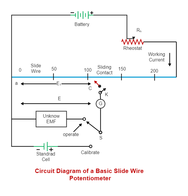
The Potentiometer Circuit Diagram below shows that a potentiometer has three pins. Two terminals (blue and green) are connected to a resistive element, and the third terminal (black) is connected to an adjustable wiper. The potentiometer can work as a rheostat (variable resistor) or voltage divider.
Customize the diagram
Customize your Potentiometer Circuit diagrams by changing the color or adding more relevant data. Based on your research, you can also add or remove the Electrical Circuit symbols or content accordingly. Since it is about electrical engineering research, you can add more relevant data about different circuit diagrams.
Export & Share
Once your required circuit diagram is completed, you can share it amongst your colleagues or clients using the easy export and share option. You can further export the diagram in multiple formats, like Graphics, JPEG, PDF, or HTML. Also, you can share the designs on different social media platforms, like Facebook, Twitter, LinkedIn, or Line. In simple words, you can export your incredible Potentiometer Circuit diagrams to the files you want with just a few clicks.
3. Important Tips to Consider While Creating Potentiometer Circuit Diagram
Always make sure to connect the circuit to the ground to avoid breakages and damages.
Check for the position of the transistor in the circuit, whether it is closed or open.
Connect the resistors wherever required to reduce the current flow and avoid damage to the Potentiometer Circuit Diagram.
Mark the value of each resistor and capacitor used in the circuit.
Use separate colors for connections wherever needed to aid users in understanding the connection.
Conclusion
The potentiometer is usually employed to find the concentration of a solute in solution. The potential between two electrodes is measured using a high impedance voltmeter in potentiometric measurements. It is recommended to use EdrawMax Online to create similar-looking circuit diagrams for your projects. It should be noted here that since these circuit diagrams are the blueprints of the actual working models, ensure that you use the correct symbols provided by EdrawMax Online.
Tag
circuit diagram
Circuit Diagram Collection
wiring plan diagram
Share
Report
2
1.7k

Post
Recommended Templates
Loading
