
Templates Community /
Arduino PID Controller
Arduino PID Controller
Community Helper
Published on 2022-04-06

 Desktop

Introduction
PID controllers are widely used in industrial and commercial applications to regulate temperature, flow, pressure, speed, and other process variables. The PID controllers have also been termed a three-term controller as it helps achieve different control actions for specific works by controlling three parameters – the proportional, integral, and derivative. Here we will look into how you can create an Arduino PID controller diagram and its core functionalities.
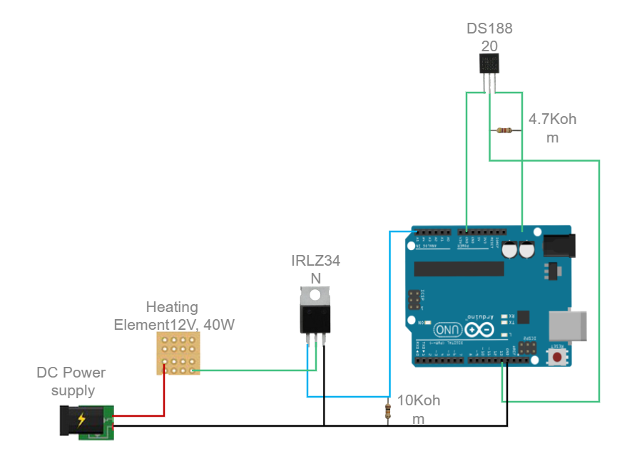
Understanding Arduino PID Controller Diagram
Arduino PID controller diagram depicts how a system assesses the feedback variable using a fixed point to generate an error signal. Each model in the Arduino PID controller diagram fulfills unique functionalities. The diagram consists of an Arduino board, which performs the main functionality, followed by the DC power supply, relay, temperature sensor, and heating element. Let us look into these modules in detail.
DC power supply - Here, it is used to power the system by converting alternating current to a stable direct current. It acts as the input part in this diagram.
Heating Element - The power generated by the DC power system is converted to heat using this element. The heating element needs to have low-temperature resistance and toughness.
Arduino board - This is the main module in this diagram. This board can read inputs and generate an alternative output. It works on simple coding.
Temperature sensor - A temperature sensor in the Arduino PID controller converts voltage to celsius and displays it.
How to Create an Arduino PID controller Diagram EdrawMax Online?
Creating an Arduino PID controller Diagram in EdrawMax Online is pretty simple. The free PID Controller maker has several features as you can instantly import the images or icons from your system or Google Drive, or DropBox. Your PID diagram will require additional media content, making it more creative.
Login EdrawMax Online
Log in EdrawMax Online using your registered email address. If this is your first time accessing the tool, you can create your personalized account from your personal or professional email address.
Choose a template
EdrawMax Online comes with hundreds of free diagram templates. Select a pre-designed template by entering the Keyword in the "Search" section or exploring different diagram sets. In this case, you will find different types of PID controllers under the "Industrial Process" section under the "Engineering" section. Alternatively, you can simply click on "+" in EdrawMax Online canvas to create a diagram of your preference.
Work on your research
It should be noted here that the PID algorithm is used to control an analog process having a single control point and a single feedback signal. The PID algorithm controls the output to the control point to achieve a set point.
Customize the diagram
Customize your Arduino PID controller diagram by changing the color or adding more relevant data. You can also add or remove the PID Controlling symbols or content accordingly based on your research.
Export & Share
Once your required Arduino PID controller diagram is completed, you can share it amongst your colleagues or clients using the easy export and share option. You can further export the diagram in multiple formats, like Graphics, JPEG, PDF, or HTML. Also, you can share the designs on different social media platforms, like Facebook, Twitter, LinkedIn, or Line. In simple words, you can export your incredible PID Controlling diagrams to the files you want with just a few clicks.
Important Tips to Consider While Creating Arduino PID Controller Diagram
A circuit diagram helps the user to understand the function. So, it is imperative to understand the functionalities of each system in the diagram and make clear connections wherever needed.
The placement of input signals has to be taken care of while creating the diagram. The connections should be made from left to right. Here the power supply stands as the input and the Arduino board as the output.
Use wiring color codes throughout the design to make clear connections.
It is imperative to show where the nets are connected and crossed over.
Mark the name of each system in the circuit to make it clear.
Conclusion
Arduino PID Controller has many applications in motor speed control, digital temperature controller, and several power electronics projects. The power generated by the DC power input is converted to heat, and then the Arduino board generates an output signal based on the input. The diagram easily depicts its function and key components. With EdrawMax Online, you can create a PID Controller for your projects. The free tool comes with free PID symbols and icons that can easily be integrated into any design.
Tag
Utility-Generation P&ID
Share
Report
5
449

Post
Recommended Templates
Loading
