
Templates Community /
Arduino PID
Arduino PID
Community Helper
Published on 2022-04-06

 Desktop

Introduction
PID or proportional integral derivatives utilize a loop feedback mechanism to regulate process variables. It is a common means of controlling temperature and has wide applications in chemical and scientific processes. A PID is a closed-loop system, which means a controller controls the output and requires multiple feedback paths. Let us understand more about it through the Arduino PID diagram.
Understanding Arduino PID diagram
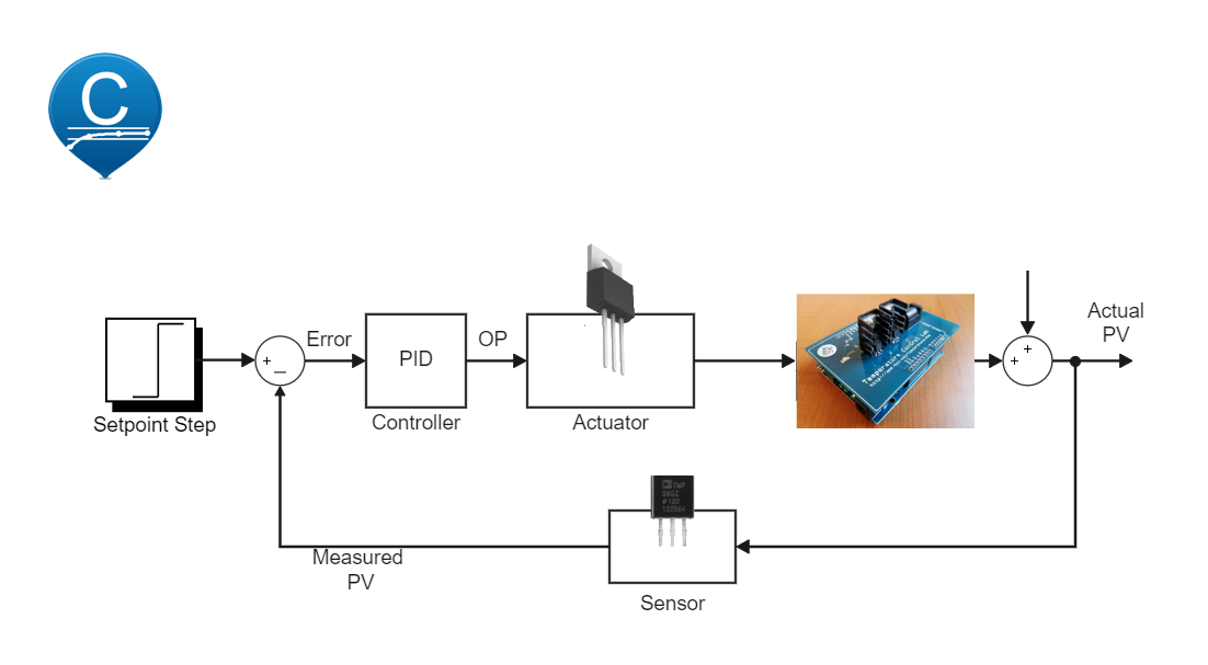
Although the Arduino PID diagram looks complex, it is not. It consists of a PID controller, actuator, temperature controller, sensor, and a setpoint step. It is a closed-loop system that is depicted in the diagram. A target value is set in the setpoint step, which is the circuit's input. It is then passed through a voltage source and the PID controller. Let us look into detail at the functions of each component in the Arduino PID diagram.
PID controller block is used to regulate pressure and other variables in this system. It uses a closed-loop mechanism. It calculates the difference between setpoint temperature and the current temperature in the loop. Identifying the difference in the temperature defines the power to be used in the next phase.
Actuator - The signal from the PID controller block is converted into a mechanical motion using an actuator. The actuator is what induces motion in the system. The signal is then passed to the temperature controller.
Temperature controller - As the name suggests, it is a device to control the temperature in the circuit. It measures the temperature in the circuit and compares it with the set or target temperature value. If the value differs, it is adjusted using this device.
How to Create an Arduino PID Diagram EdrawMax Online?
Creating an Arduino PID Diagram in EdrawMax Online is pretty simple. The free PID Controller maker has several features as you can instantly import the images or icons from your system or Google Drive, or DropBox. Your PID diagram will require additional media content, making it more creative.
Login EdrawMax Online
Log in EdrawMax Online using your registered email address. If this is your first time accessing the tool, you can create your personalized account from your personal or professional email address.
Choose a template
EdrawMax Online comes with hundreds of free diagram templates. Select a pre-designed template by entering the Keyword in the "Search" section or exploring different diagram sets. In this case, you will find different types of PID controllers under the "Industrial Process" section under the "Engineering" section. Alternatively, you can simply click on "+" in EdrawMax Online canvas to create a diagram of your preference.
Work on your research
As you will see from the research below, a PID controller seeks to keep some input variables close to the desired setpoint by adjusting an output. How it does this can be 'tuned' by adjusting three parameters.
Customize the diagram
Customize your Arduino PID diagram by changing the color or adding more relevant data. You can also add or remove the PID Controlling symbols or content accordingly based on your research.
Export & Share
Once your required Arduino PID diagram is completed, you can share it amongst your colleagues or clients using the easy export and share option. You can further export the diagram in multiple formats, like Graphics, JPEG, PDF, or HTML. Also, you can share the designs on different social media platforms, like Facebook, Twitter, LinkedIn, or Line. In simple words, you can export your incredible PID Controlling diagrams to the files you want with just a few clicks.
Important Tips to Consider While Creating Arduino PID Diagram
While the diagram looks simple, following the connections without error is imperative. Any error in the diagram will impact the complete circuit.
Connect the main components, including the temperature control device and PID controller, in series with each other.
The output of the PID controller is connected to the actuator.
The output of the temperature control device is connected back to the sensor. Moreover, if the temperature matches the set value, it is moved to the next phase.
In the setpoint step, set the temperature.
Try connecting the circuit from left to right that is input to an output format.
Conclusion
The Arduino PID is used to regulate the temperature in the system. So, its use cases are majorly related to the automotive sector, like cruise control. The circuit diagram is self-explanatory if you understand the functions of each device. With EdrawMax Online, you can create a PID Controller for your projects. The free tool comes with free PID symbols and icons that can easily be integrated into any design.
Tag
Utility-Generation P&ID
Share
Report
3
188

Post
Recommended Templates
Loading
