
Template Community /
Auber PID
Auber PID
Community Helper
Published on 2022-04-06

Introduction
A simple, versatile feedback compensator structure or PID is widely used in industrial applications to regulate temperature. It works in a closed-loop system. The popularity of the PID controller can be attributed to its straightforward usage. Its three coefficients, namely, proportional, integral, and derivative, are varied in the system to get optimal output. The Auber PID circuit diagram lets us understand its components and work more.
Understanding Auber PID Circuit Diagram
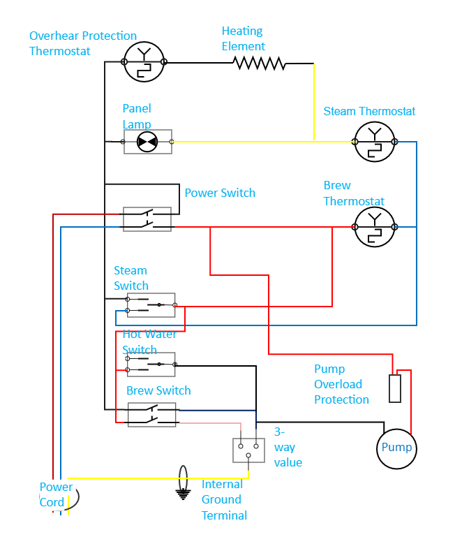
While the circuit diagram looks quite complex, it is not so. The Auber PID controller has multiple components connected in parallel with each other. Different components perform different functions to derive the output. Let us look at each of them in detail.
Power Cord - At the input side, we have the power cord. We can connect the circuit or the system to the electricity supply using the power cord, connecting to the power switch.
Power Switch provides the electrical connection from a voltage source to a load in this circuit. It is connected to the steam switch, power switch, panel lamp, hot water switch, and brew switch.
Overheat protection thermostat - This circuit is imperative to regulate the temperature. It protects the system from breakage due to overheating.
The 3-way valve has a major role in this circuit and is connected to hot water and brew switches. It functions as a two-inlet, single-outlet system, redirecting part of the flow in another direction.
Thermostat - Three different thermostats, namely, overheat protection, brew, and steam thermostat, are used in this circuit. The steam thermostat is used to regulate the temperature in the complete circuit. It helps keep the device's temperature at an optimal or set value.
Power Overload Protection - Circuit breakers and fuses can also be used in the place of power overload protection. It protects the device from breakage or damage from over power supply.
How to Create an Auber PID Diagram EdrawMax Online?
Creating an Auber PID Diagram in EdrawMax Online is pretty simple. The free PID Controller maker has several features as you can instantly import the images or icons from your system or Google Drive, or DropBox. Your PID diagram will require additional media content, making it more creative.
Login EdrawMax Online
Log in EdrawMax Online using your registered email address. If this is your first time accessing the tool, you can create your personalized account from your personal or professional email address.
Choose a template
EdrawMax Online comes with hundreds of free diagram templates. Select a pre-designed template by entering the Keyword in the "Search" section or exploring different diagram sets. In this case, you will find different types of PID controllers under the "Industrial Process" section under the "Engineering" section. Alternatively, you can simply click on "+" in EdrawMax Online canvas to create a diagram of your preference.
Work on your research
As you will see from the image below, the working principle behind a PID controller is that the proportional, integral, and derivative terms must be individually adjusted or "tuned."
Customize the diagram
Customize your Auber PID diagram by changing the color or adding more relevant data. You can also add or remove the PID Controlling symbols or content accordingly based on your research.
Export & Share
Once your required Auber PID diagram is completed, you can share it amongst your colleagues or clients using the easy export and share option. You can further export the diagram in multiple formats, like Graphics, JPEG, PDF, or HTML. Also, you can share the designs on different social media platforms, like Facebook, Twitter, LinkedIn, or Line. In simple words, you can export your incredible PID Controlling diagrams to the files you want with just a few clicks.
Important Tips to Consider While Creating Auber PID Circuit Diagram
Before you design the circuit, it is important to understand the symbols used for each component. It makes it easier to design and connect the circuit. Apart from this, certain other things need to be taken care of while designing the circuit or the system. Some of them are:
Cross-check all the parallel connections and make connections smoothly
Check whether there are any cross-connections to avoid breakages
Make sure to connect the power overload protection to avoid power breakages or damages throughout the system.
Always connect the internal ground terminal in the circuit without fail
Check if the switches connected are closed or open in the circuit.
Conclusion
The Auber PID controller has wide applications in today's market. Easily regulate the temperature using the system. With EdrawMax Online, you can create PID Controller for your projects. The free tool comes with free PID symbols and icons that can easily be integrated into any design.
Tag
Utility-Generation P&ID
Share
Report
0
51

Post
Recommended Templates
Loading
