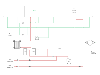
The image is a technical Piping and Instrumentation Diagram (P&ID) for a fluid system, commonly used in engineering to detail the piping and related components of a physical process flow. This P&ID outlines the flow paths, valves, pumps, and other equipment within the system. The diagram uses standard symbols to represent the physical components. Red lines indicate the primary flow of the fluid, while green lines might represent secondary or auxiliary flows. Valves are indicated by symbols resembling small diamonds, and the direction of flow is indicated by arrows. Two pumps are represented by circles with fan-like symbols inside them, and what appears to be a heat exchanger is depicted with a set of parallel lines. The system includes annotations such as "To Sump," "To Reservoir," "From Reservoir," "To Sizer Spray," and "From Face Plate," providing context for the fluid's path and the system's operation.