Template Community /
Relay Driver Circuit Wiring Diagram
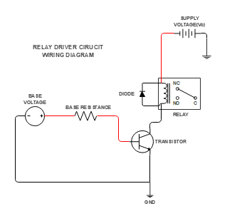
Relay Driver Circuit Wiring Diagram
User 101
Published on 2024-03-03

A relay driver circuit is an essential component in controlling relays using low-power electronic devices like microcontrollers or Arduinos. It ensures that the relay coil operates reliably and protects other components in the circuit.
The transistor acts as a switch to control the relay coil. When the base voltage is applied, the transistor allows current to flow through the relay coil. Connected in parallel with the relay coil, the diode suppresses voltage spikes generated when the relay turns off. It prevents damage to nearby components.
When the input signal activates the transistor, current flows through the relay coil. The relay switches from an open to a closed position. Turning off the transistor interrupts the current flow. The relay coil reacts by producing a voltage spike. The diode suppresses this spike, protecting the transistor and other components.
Tag
IT
electronics
ELECTRICAL ENGINEERING
Relays
Relay Driver Circuit
Share
Report
0
29

Post