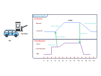
In the following timing diagram of the vehicle toll system, there are two components: the vehicle barrier and the ticket machine. Each component is represented by a square box, and its states are shown on the right. A timeline is shown below, showing different situations over time. Initially, both sections are idle, and the car barrier is lowered. When the user inserts a coin into the ticket machine, it validates the coin and raises the barrier. After a duration of T 8s, the barrier drops again and the machine returns to the idle state. This diagram effectively shows the sequential operations of vehicle toll System components.