Deployment Diagram Explained
Create a Deployment Diagram Online Free Free Download Free Download Free Download Free DownloadUML Deployment Diagram describes the software system's specifications and the physical hardware system required to run the software. The Deployment Diagram also determines the installation of the software on the hardware. UML Deployment Diagram maps software segments of a method to the device that is going to implement it.
What is a deployment diagram in UML?
The deployment diagram plans the software planning generated in a blueprint to the physical system planning that runs it.
When to use a deployment diagram?
- To ensure the needs of existing systems, the newly added system needs to interact with the old system.
- To check how robust the system needs to be in case of hardware system failure.
- To ensure the connectivity of the policies and how they interact and to check their functioning.
- To make the individual what interface, including the operating system and communications approaches and protocols, will system use.
- To check what software and hardware will users directly interact with on the network.
- To observe the system after deployment.
- To check how secure the system needs to be and check the requirement of a firewall, physically secure hardware, etc.
Uses of deployment diagrams
- The run-time system structure is shown with its use.
- The Deployment Diagram apprehends the hardware and the connections between the different parts of the device to execute the method.
- The diagram defines connection routes between the physical hardware elements.
- Planning of the architecture of the system is done by using the picture.
- The implementation of software components is easily documented by using the diagram.
Deploymnet diagram symbols
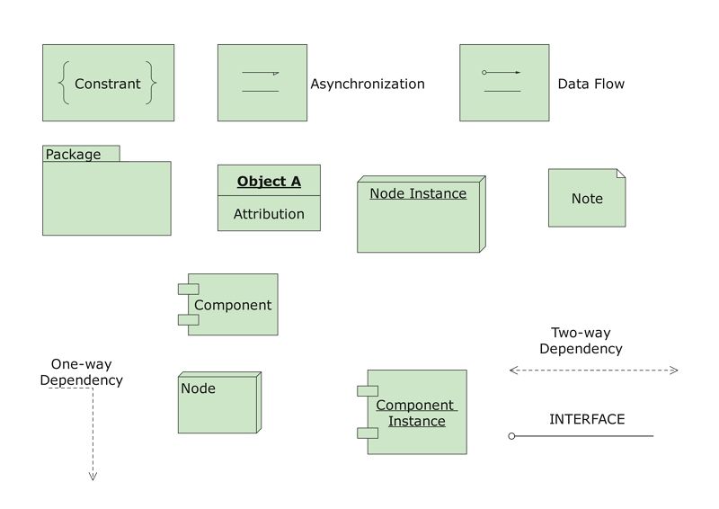
A deployment diagram contains the following symbols:
- Artifacts
- Source files
- Executable files
- Database tables
- Scripts
- DLL files
- User manuals or documentation
- Output files
- Nodes
- Association
- Stereotype
An artifact constitutes the definition of a tangible physical-world establishment connected to software programming.
During the process of software development or some executable file, the object can be used to describe the framework. Deployment of the artifacts is done on the nodes. The most regular artifacts are listed below.
Nodes are used for the deployment of Artifacts. UML elements get concrete demonstration through its application. Node is an adaptive asset on the subject of which artifacts are positioned for implementation. A node is a physical object that can implement one or more artifacts. A node can range in its value be conditional on the magnitude of the intended.
Node is a crucial UML component that narrates the implementation of code and the transmission among different system structures. It is symbolized by a three-dimensional box with the node-name on it.
Quick Fact: A node as a container means that a node contains another node inside it, such as in the example below, where the nodes contain components.
Association is a line that stipulates a communication or new sort of transmission among nodes. An association constitutes a conveying route between nodes.
The stereotype is a device which is contained within the node. It is presented at the top of the node, with the name bracketed by double arrows. There are various standard stereotypes that are provided for nodes. A few of them are «user pc», «cdrom», «cd-rom», «computer», «disk array», «pc», «pc client», «pc server», «secure», «server», «storage» and «Unix server». The standard stereotypes show an icon in the top right corner of the node symbol.
Deployment diagram examples
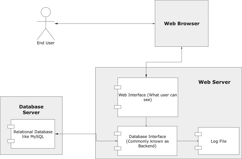
The first example depicts how a user foresees something available to him on the internet using a web browser. But he is unaware of the web and database servers while he browses the net. Whenever a user generates a query, the Web Browsers instantly connects with the Web Server. There are three major components related to it:
- Web Interface: Normally referred to as UI/UX.
- Database Interface: The backend where all the queries are executed.
- Log File: An array of information stored about the previous searches.
When the user asks for a result, the web browser checks into the database to generate the result and display the result to the End User on his computer screen.
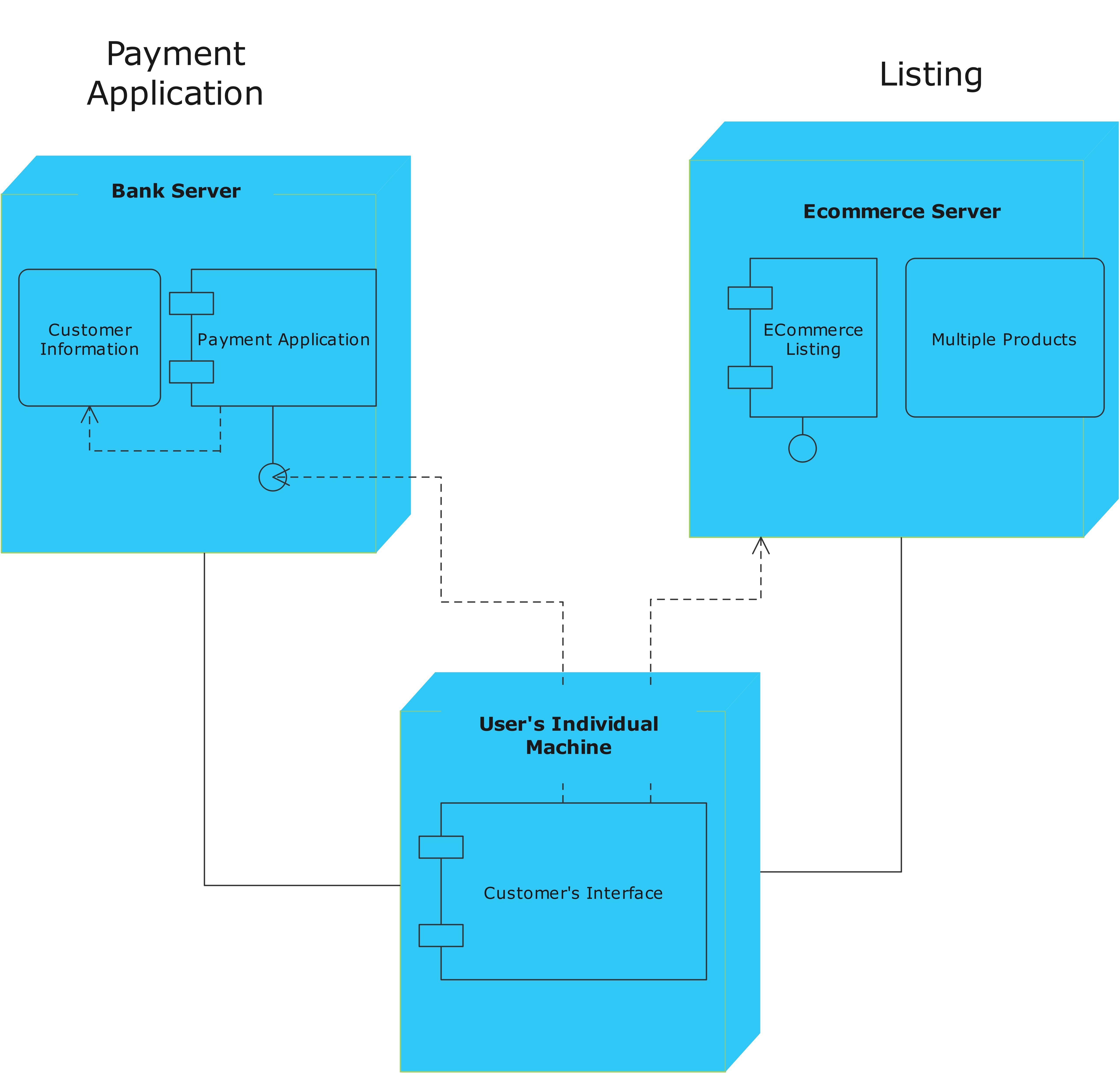
This is a simple example of how an E-commerce platform generally works. It shows how a user goes to an online platform to purchase something. To successfully place an order, he will first have to check the listing available on the E-Commerce website's server, denoted here by a package and subsequent component. After selecting the product, the query redirects to the bank where all the banking transactions happen. This is indicated here by the box titled Bank Server.
Key takeaways
The UML deployment diagram maps the software pieces of a system to the hardware that will execute it. The deployment diagram visualizes the topological view of an entire system. Artifacts and nodes are the essential elements of deployment. The artifacts and nodes of a system participate in the final execution of a system.


