State Diagram Explained
Create a State Diagram Online Free Free Download Free Download Free Download Free DownloadWhat Is A State Diagram in UML?
A UML state diagram is a behavioral diagram used to represent a system's conditions at a given time. It shows the changes in the system in response to factors such as time and other events.
Why Use A State Diagram?
A state can be defined as a set of values that define an object, which is grouped together based on characteristics that can affect an object or system's overall behavior. State diagrams are used to depict the states and the transitions between states. Other uses for state diagrams include:
- Modeling the dynamic aspects of a system’s behavior
- Depicting how objects transition between various states during its perpetual
- Exploring how and why certain external and internal factors can cause objects to react in a particular way
State Diagram Symbols
Here is a list of commonly used symbols and notations when drawing a UML state diagram.
 |
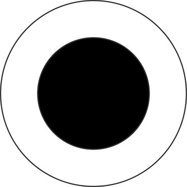
Initial
A solid black circle symbolizes the initial state of the system. |
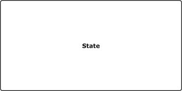 |
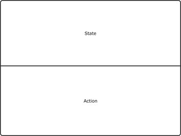
State
A state is represented by a rounded rectangle. |
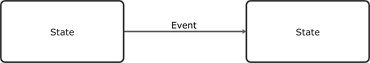 |
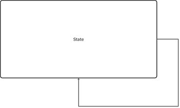
Transition
An arrow - labeled with the event that causes a state change - between two states represents a transition. |
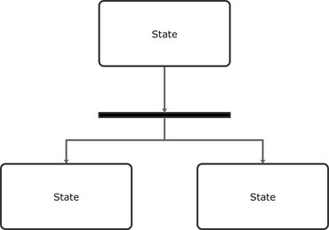 |
Fork
A fork symbolizes a state being split into two or more concurrent states. |
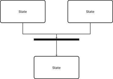 |
Join
A join symbolizes two concurrent states converging into one. |
 |
Self transition
When an object's state doesn't change upon an event's occurrence, this is known as a self transition. |
 |
Composite State
A state with internal activities occurring on the inside is known as composite states. |
 |
Fork |
How to Draw A State Diagram in EdrawMax?
EdrawMax’s intuitive software allows you to create your own state diagrams. Whether it’s a basic or complex one, follow this outline to create one that fits your needs.
- Step 1: In your browser, visit https://www.edrawmax.com/online/ to access the online version, or download the desktop version at https://www.edrawsoft.com/download-edrawmax.html
- Step 2: In the white sidebar, click on Software Development. Then, click on the UML Modelling box that appears near the top of the screen.
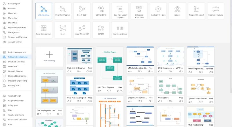
- Step 3: Choose a template, or click on the UML Modelling box with the “ + ” to open a new document.
- Step 4: The symbol library can be found to the left of the screen. Scroll down further to find more UML-related symbols. Once you’ve selected the symbols you need, click ‘OK’ and add the shapes to the toolbar on the left.
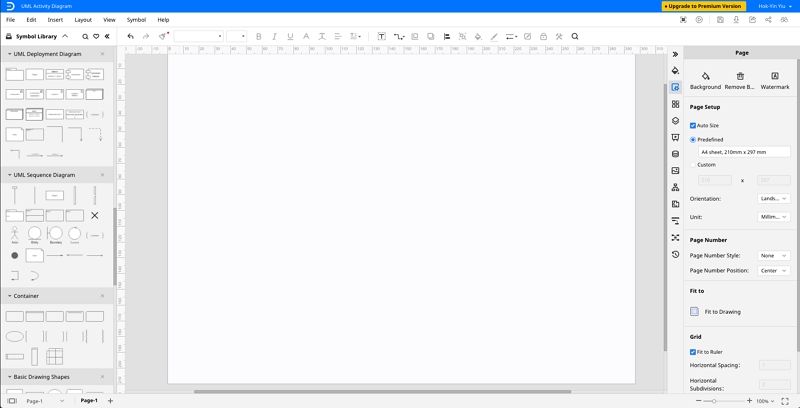
- Step 5: Simply drag the components you need from the symbol library onto the blank document to start creating. Each element can be moved, resized, or customized to fit your needs.
State Diagram Examples
Diagram 1: State diagram - checking calendar availability
This is an example of chekcing calendar availability.
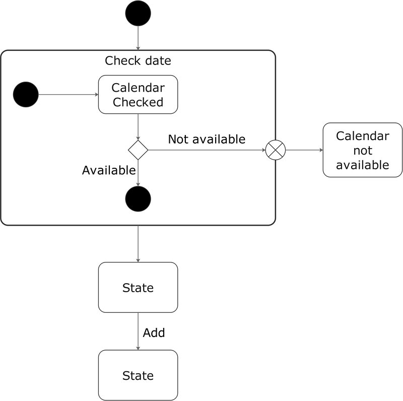
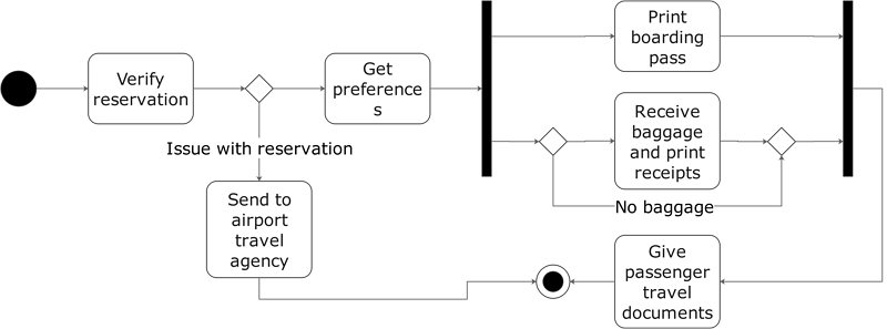
Diagram 2: State diagram - processing an airline passenger
This is an example about the process of airline passenger.
Summary
UML state diagrams are a useful tool for software developers and business users alike to map out a system's behavior. Be sure to try out EdrawMax, making drawing diagrams such as these so simple and intuitive.