Collaboration Diagram Explained
Create a Collaboration Diagram Online Free Free Download Free Download Free Download Free DownloadWhat Is A Collaboration Diagram in UML?
Collaboration diagrams are also known as communication diagrams. They can demonstrate how objects communicate to execute a specific use case's actions or an aspect of a use case. Designers can use collaboration diagrams to explain and identify the roles of objects performing a specific flow of events in a use case. They are the main information source used to establish class roles and interfaces.
Collaboration diagrams are developed by first determining the design elements required to incorporate the functionality of interface features. The interactions among these elements are then used to build a model. The aim of a collaboration diagram is to illustrate the systemic dimensions of a structure, i.e., how various lifelines link within the structure. Collaboration is a set of named actions and systems which have connections to them. They work together to perform any task.
Through interacting together, objects may generate (usable) high-level functionalities. The objects collaborate and operate together by communicating (passing messages) with each other. The collaboration diagram represents the relationships between the objects. The collaboration diagram illustrates how messages are exchanged between classes and objects (instances). It is generated for each process of the system and relates to the existing development phase.
Application Scenarios for Collaboration Diagrams
Few examples of situations where collaboration diagrams may be beneficial include:
- Create a birds-eye view of a collection of objects collaborating, especially within a real-time system.
- Allocate capability to classes by exploring a system's behavioral attributes.
- Modelling collaborations, processes or hierarchical organization in the architecture of a system.
- Providing a description of objects operating together within an object-oriented framework.
- To display multiple alternate possibilities for the same use case.
- To illustrate forward and reverse engineering.
- Capturing information passing between objects.
- To visualize the complex logic of a system.
Benefits of a Collaboration Diagram
- It reinforces the structural aspects of an interaction system which is how the lifeline is connected.
- Messages transmitted over sequencing are shown by hierarchical numeration of each message.
- It enables to focus on the structural elements and not on the flow of message as stated in sequence diagrams.
Drawbacks of a Collaboration Diagram
- Exploring every object in the diagram is not easy.
- An object’s state changes frequently, which makes it troublesome to keep track of every change in every object present in the system.
- There are instances when there are too many objects present in the collaboration diagram and this can crowd the diagram.
Relations Between Collaboration Diagram and Sequence Diagram
Sequence diagrams and collaboration diagrams display the same details, but simply present it differently. Within UML the collaboration and sequence diagrams are the two forms of interaction diagrams. While both styles use relevant and similar data, they present the information in different ways.
Collaboration diagrams have been used to envision the structural organization and interactions between objects. At the other hand, sequence diagrams concentrate on the order of messages moving in between objects. Nonetheless, a single figure is not enough in most situations to explain a system 's behaviour, so both diagrams are necessary.
Symbols and Components of Collaboration Diagram
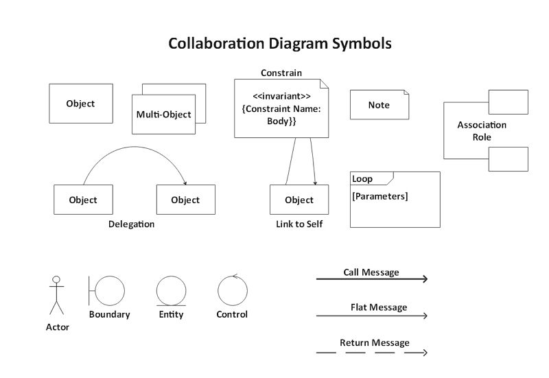
- Links: Links connect objects as well as actors. These are cases of associations, and each link within the class diagram relates to a connection.
- Actor: Typically an instance of the actor exists as the beginning of the interaction in the relationship. If multiple instances of actors are present in the same diagram, focus on keeping them towards the outside of the diagram.
- Object: An object is depicted by an object symbol displaying the object's name, and underlining its class, differentiated by a colon.
- Message A message is an interaction between objects conveying information with the belief that the action will follow. A message is displayed in collaboration diagrams as a labelled arrow, located near a link.
How to create a collaboration diagram with EdrawMax?
The UML collaboration diagram can be illustrated by designing objects in a structure and illustrating the connections between the objects as links. Given below is a step-by-step guide to creating a collaboration diagram with Edraw Max.
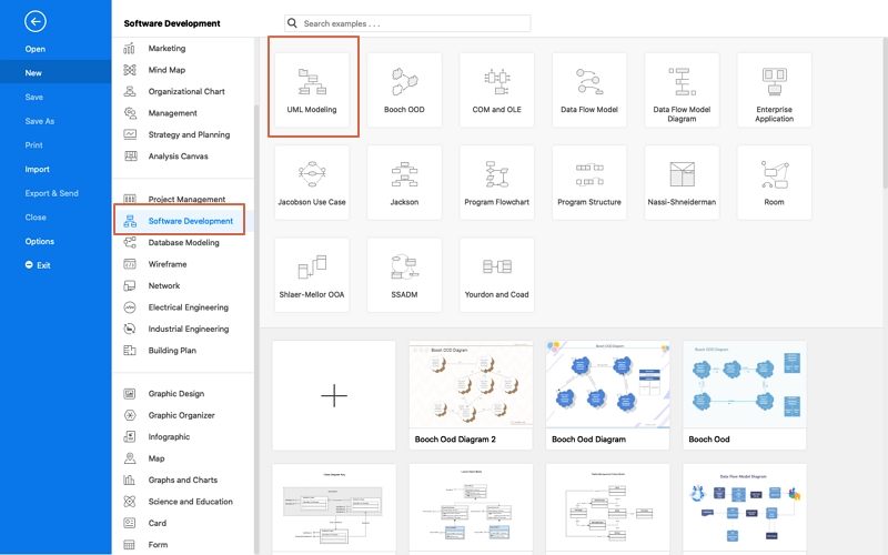
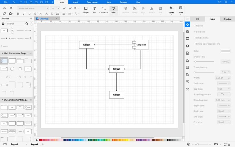
- Step 1: Open a UML Diagram template.
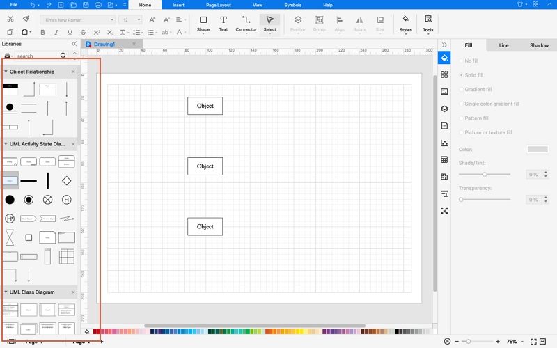
- Step 2: Add UML Collaboration Diagram Shapes.
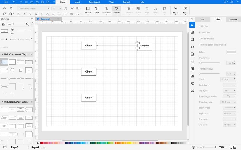
- Step 3: Connect shapes in the diagram using connectors to create the UML collaboration diagram.
- Step 4: Double click and type in the content for the UML collaboration diagram.
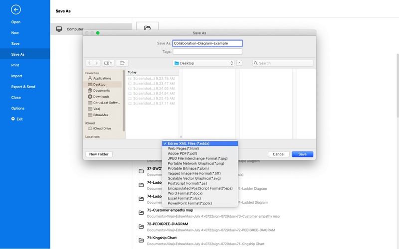
- Step 5: ‘Save’ and ‘Export’ your diagram.
Click on new, select Software and then pick UML Model Diagram.
Collaboration Diagram Examples
Diagram 1: Purchase Journey
In this example, a collaboration diagram of the purchase journey of a consumer on an e-commerce website is illustrated. It depicts the order of purchase from the ‘Item’ object to the message of ‘order details’ being displayed.
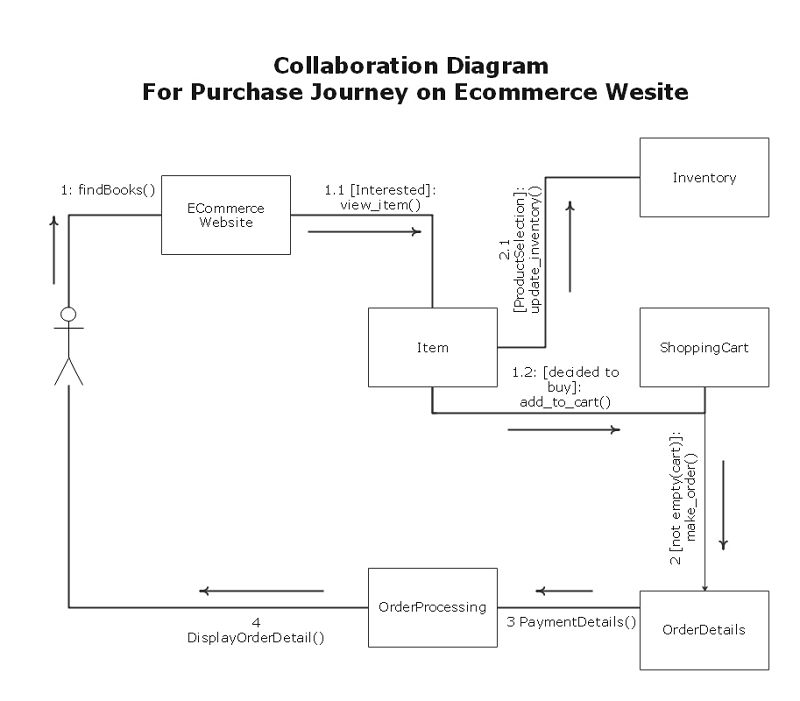
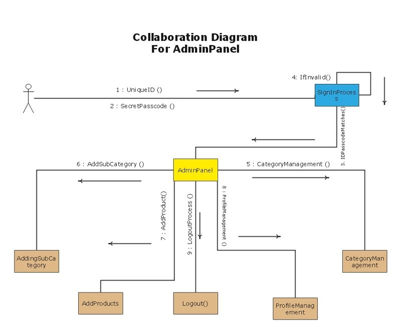
Diagram 2: Admin Panel
This example depicts a collaboration diagram of an admin panel. It shows the user signing in using their unique Id to access an interface of profiles, products, etc.
Summary
Collaboration diagrams are particularly well suited for depicting simplistic interactions between small numbers of objects. While collaboration diagrams are not used as frequently as sequence diagrams, they are an incredibly useful aspect of UML. It helps to envision, in a single diagram, all the complex dimensions of collaboration and the relationships between objects.


