Component Diagram Explained
Create a Component Diagram Online Free Free Download Free Download Free Download Free DownloadWhat Is A Component Diagram in UML?
The components of any system are an integral part. The graphical depiction of these components and their wiring with each other in the form of a diagram is called a ‘Component diagram or UML component diagram.’ It is a modular representation of software-components and their inter-dependencies. The collection of these multiple components, in which each component has a unique set of functions in the entire system. For the planned development of a system these component diagrams are drawn to re-test the various aspects of the system.
A component diagram UML represents various high-level functionalities of an actual system. It helps to visualize the different elements of any system. For eg: in UML 2.0, the various elements for a business can be- buyers, commerce, backend, profits, sales, etc are visualized via the component diagram. The UML helps to link these elements together and creates a better understanding of the concepts.
What is a component diagram UML used for?
A component diagram UML is used majorly to modelize the subsystems. Primarily it is used to fulfill the following objectives:
- To graphically visualize the various components of a system during run-time.
- To describe the components used to constitute the functionalities of the system.
- To use forward and reverse engineering in order to build executables.
- To act as a catalyst for the testing of a system.
When/where is the UML component diagram needed?
The following are some benefits of a Component diagram:
- Acts as an integral part of building the software’s system.
- Visualize existing processes and strategize future ones.
- Imagine the service impact of the output.
- Provides structure on the wiring or relation of various processes of the system.
Symbols and components of component diagram
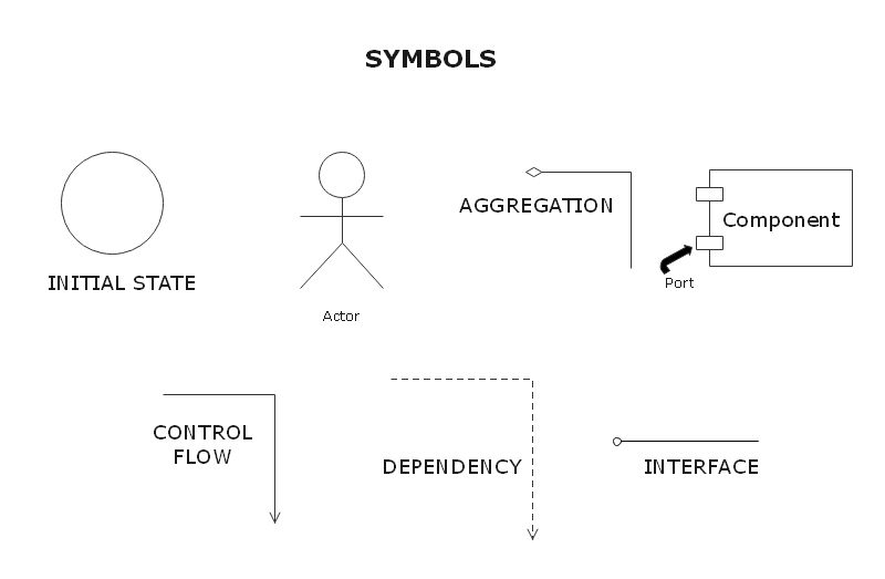
It is important to understand the imperatives of a component diagram. The following are the basic symbols and components of a component diagram:
Interface
An interface is used to describe a group of various operations made by components. A complete circle denotes an interface created or provided by a component whereas a half-circle denotes a required interface, e.g.: someone’s input.
Port
A port is an interaction point between a classifier and an external environment. It groups a semantically cohesive set of provided and required interfaces. A port can be used in UML without a specific name. The port is public if drawn over the boundary of the classifier which also denotes that all interfaces being used are made public.
Component
Component- It is a logical unit that acts as the basic block of the system. It is denoted Component details are hidden for the external environment. The name of a component is placed at the center. Optionally, the upper right corner of the rectangle displays a component icon.
EdrawMax Tips for creating component diagrams:
- Explore every component of the system in detail in order to understand the relation of a component to other physical artifacts.
- Designate a graphic or visual for each component.
- Use annotations and symbols mentioned above to represent the relationship between various components.
- Libraries, files, and artifacts and their inter-related relationships are imperatives during modeling of your component diagram.
How to draw a UML component diagram with EdrawMax?
Follow the below-mentioned steps to create UML component diagrams.
- Start EdrawMax, click Software, then double click the UML model diagram to open a blank drawing page.
- Drag and drop relevant UML symbols from left libraries or click the floating buttons to add automatically.
- Double click the symbols and text the information.
- Drag the proper connector from left libraries to connect symbols.
- Browse your computer and choose a location to save your UML component diagram.
Component Diagram Examples
Diagram 1: E-commerce
The above mentioned component diagram example shows the relationship of various components of an e-commerce business system namely: products, buyer, reliability and endurance.
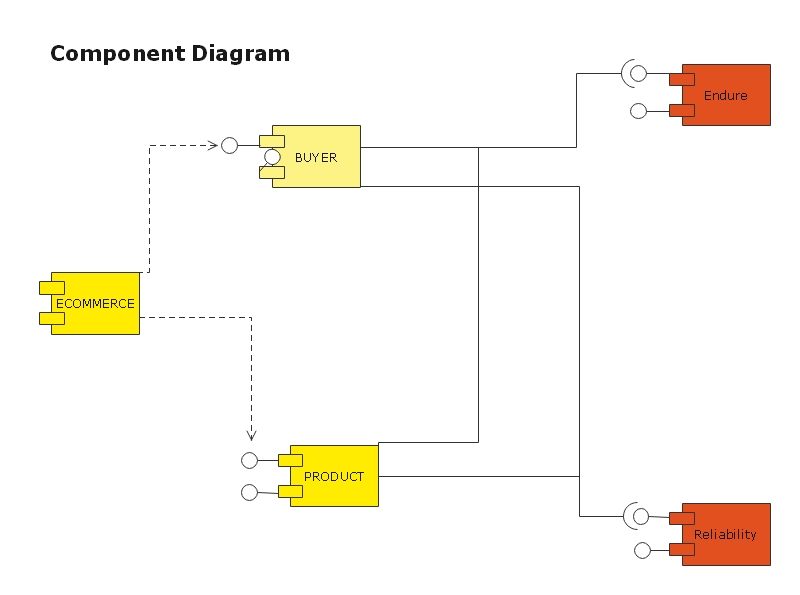
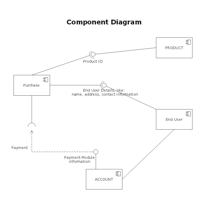
Diagram 2: Business
In an e-commerce business productivity/profit relies on the product and buyers. The product and buyers are interfaces imposed by the business which are proportional to the backend support that is reliability and endurance. The Components reliability and endurance need direct involvement of personnel. These components remain hidden whereas Product and buyer remain visible actively.
Key Takeaways
- Any component diagram is the visual representation of any system.
- All components pose a set of interfaces imposed by a component.
- UML component diagrams static as well as a dynamic presentation.
- The model of any component diagram UMLconstitutes all the various components of the system.


